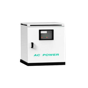
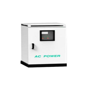
ER-PS-400W Solid-State GPU 400Hz Frequency Converter
Our 400hz frequency converter is the most reliable solutions on the market today. It is used in all types of aircraft under the harshest environmental conditions. Our products have quality assurance, free replacement within one year, if you are interested, please contact us.
ER-PS-400W Solid-State GPU 400Hz Frequency Converter, as the power source for the development of aircraft quality 400Hz power supplies, it is mainly used in aircraft production manufacturing, aviation R&D, military/civil hangar, maintenance plants, aerospace equipment, military airport tarmac and wells, aviation factories.
ER-PS-400W series is one of the most popular static frequency converters. ER-PS-400W is designed to change the power at 50Hz or 60Hz to aircraft quality power at 400Hz.
400hz frequency converter integrates IGBT made by Mitsubishi, Siemens and Infineon with PWM switching technology, and combines micro controller and digital signal processor (DSP) for quicker response and higher reliability.
Features
Automatically voltage compensation system, ideal voltage at aircraft connector
Self diagnose system which would show error code/faulty explanation on the VFD screen
Memory stores 10 events
Galvanically isolated, low harmonic distortion
Thoroughly proven advanced SPWM and IGBT technology
Pure sine wave output
Eco-friendly, high efficiency, low noise
28VDC military interlock
Specifications
| Capacity | 30/45/60/90/120/150/180KVA |
| Input | Voltage: 3 x127V/220V±15% or |
| 3 x220V/380V±15%, | |
| 3 x240V/415V±15% | |
| Or according to your specific requirement | |
| (select one individual voltage) | |
| Frequency: 40-70Hz | |
| Power Factor: | |
| ≥0.8 (Standard type) | |
| ≥0.9 (12 pulse type, optional item) | |
| Inrush current: None, soft start | |
| Output | 3×115/200V, 3×120/208V (L-N/L-L), |
| Or select one individual voltage | |
| Frequency: 400Hz (320-480Hz adjust) | |
| Interface: RS232/485 communication port | |
| Voltage regulation: ±1% FS (full scale) | |
| Frequency regulation: ±0.1% | |
| Crest: 1.414±0.1 | |
| Distortion: THD<3% @ linear load | |
| Voltage difference between each phase<3V | |
| Line drop compensation: 1-10V | |
| Voltage recovery: ∆U <10% and rec. time <50 ms at 100% load change |
|
| Phase angle symmetry: | |
| 120°±2° (33% unbalance load) | |
| 120°±4° (100% unbalance load) | |
| Overload | 125% for 600 sec; |
| 150% for 60 sec; | |
| 200% for 10 sec. | |
| Protection | Input over/under voltage, phase loss |
| Over current, over load, | |
| Inner overheating, short circuit, | |
| Output phase loss, wrong phase sequence | |
| Self diagnosis and alarm | |
| VFD display and control | Output voltage, current, frequency |
| Start/Stop, on/off each output | |
| Line drop compensation status | |
| Emergency stop | |
| Available options | 28 VDC, 300-3000 A (45-180KVA only) |
| Additional output contactor | |
| Remote control box | |
| Terminal extension for 2 PCS of 7 core cable | |
| Parallel system | |
| Door interlock | |
| 28V military interlock | |
| Working condition | Temperature: -40 to 55℃ |
| Humidity: 10~95% non condensing | |
| Noise: <65dB within 1 meter | |
| IP22 / IP55 | |
| Reliability & Efficiency | Mean Time Between Failure (MTBF) 50,000H |
| Mean Time To Restoration (MTTR)<30 min | |
| Electromagnetic compatibility: Meeting relevant requirement of IEC61000-6-2 and EC61000-6-4 |
|
| Standby power consumption: <65W | |
| No-load power consumption: <2.5KW | |
| Efficiency: ≥85% at full load for standard type | |
| ≥95% at full load for 12-pulse type (Optional) | |
| Standards | DFS400 |
| MH/T6018 | |
| ISO 6858 | |
| MIL-STD-704F | |
| EN62040-1-1 | |
| GJB572 | |
| EN61000 | |
| GJB 181 |
Application Techniques
1.What is the Device Interface Definition of MEMS North Seeker
2.What Performance is the FOG sensor in FOG North Finder
3.Where are MEMS Gyroscopes Used?
4.Research Background and Current Status of MEMS IMU
5.How do parameters affect the performance of the quartz accelerometer?
6.Background and Development Status of MEMS Inertial Sensors
More Products
