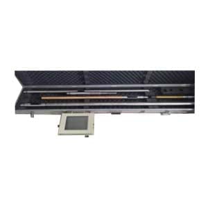
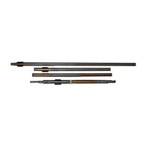
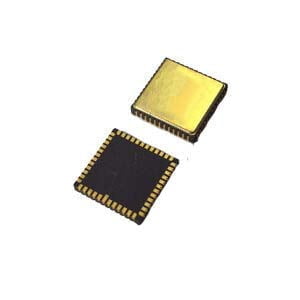
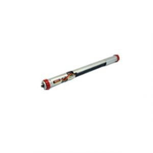
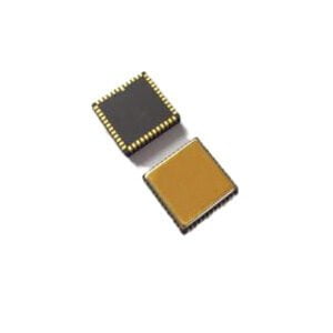
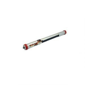
MWD is a wireless measurement while drilling system powered by a downhole turbine generator. The instrument is based on a fixed encoding of the downhole parameters measured by the probe sensor to generate a pulse signal that controls the pulse generator to expand and contract In order to control the mud circulation area between the mushroom head and the restrictor ring. When the mushroom head retracts, the mud in the drill string can smoothly pass through the restrictor ring: when the mushroom head is raised, the mud circulation area is reduced, thereby generating a positive mud pressure pulse in the drill string. The pressure sensor connected to the riser converts the received pressure signal into an electrical signal. It is transmitted to the computer through the explosion-proof box and interface box. The signal is filtered, decoded, and calculated to obtain the downhole measurement parameters.The mud flow area between the mushroom head and the restrictor ring determines the strength of the signal. The use of different restrictor rings can make the instrument work in different wellbore, different displacement and different working conditions. Obtain a pressure signal of ideal amplitude.
MWD is the process by which certain information is measured near the bit and transmitted to the surface without interrupting normal drilling operations.
Types of information:
(1) Directional data (inclination, azimuth, tool face Angle);
(2) Formation characteristics (gamma ray, resistivity logging);
(3) Drilling parameters (weight on bit, torque, revolution).
The sensors are housed in special downhole instruments that are part of the entire BHA. There is a transmitter in the downhole instrument that sends the signal to the surface via some kind of telemetry channel. The most common telemetry channel used today is the drilling fluid column within the drilling string. After the signal is detected on the ground, it is decoded and processed to provide the required information in a convenient and usable manner. The biggest advantage of MWD is that it can "see" what is happening in the borehole in real time, improving the decision making process by delaying measurements from the bottom of the borehole to the surface in just a few minutes.
Due to the complexity and variability of drilling conditions, there is a greater demand for the size and accuracy of drilling equipment. Small Diameter Measurement While Drilling (MWD-Φ38mm) is a kind of small-path mud pulse wireless in-drilling inclinometer,is used for conventional borehole construction, and rubber wings with different diameters (drill collar diameter of 50.8mm, 71.4mm) can be selected according to the situation of drilling tools in the field to adapt to different drilling tools. Also used in conventional large hole construction, the mud and water circulation area of non-magnetic drill collar is relatively increased, which reduces the erosion of drilling equipment and drilling tools, and is conducive to the safe construction of the well team. It is more suitable for the second and third development of oil well and small hole operation such as window sidetracking. Also suitable for use with coiled tubing to connect MWD.
Character
1. Signal telemetry channel
The methods to realize MWD telemetry include hard wire method, electromagnetic wave method, acoustic wave method and drilling fluid pulse method. At present, the drilling fluid pulse method is widely used, and the pressure pulse is transmitted to the surface through the fluid column in the drill pipe at the speed of 1200 ~ 1500m/s. All downhole components are housed in non-magnetic drill collars. Because the components of the MWD tool are to be accommodated, the bore diameter is larger than that of ordinary drill collars.
2. Pulse generator
There is a downhole controller in the MWD downhole instrument, which is a downhole CPU composed of a single board mechanism, and its role is to coordinate and control various work sequences of the MWD instrument. The downhole controller converts the parameters measured by various downhole sensors into electrical signals, and then directs the pulse generator to convert these signals into drilling fluid pulse signals in a specific sequence and format (code), and sends them upward through the drilling fluid column in the drill pipe to the ground sensor, signal decoding and data processing system, and carries out signal pickup, conversion, decoding and processing for the operator Line analysis decision.
3. Engineering parameter sensor
Common MWD is mainly to measure the well track parameters, namely the inclination and azimuth, and the tool face Angle (ω) when sliding drilling with downhole power drilling tools. Sensors that measure these engineering parameters are also called orientation sensors.
4. MWD ground system
Most MWD companies use fairly similar surface equipment to interpret, record, and display data measured by downhole sensors. The number of ground equipment depends on the company and the number of parameters being measured. If only directional data is required, the MWD company may require only a riser pressure sensor and a receiving/processing system that can be installed in the driller's duty room. If formation evaluation data and drilling data are also measured, it is practical to install all electronic and mapping equipment in the drilling fluid logging room or in a specially built house on the drill floor.
If you want to get more details about MWD,pls visit https://www.ericcointernational.com/north-finding-system/mwd/
More Technical Questions
1.Development of MWD for Directional Drilling
2.GWD – Gyro-while-drilling Technology Superior to Traditional MWD
3.Three Signal Transmission Methods of MWD Inclinometer While Drilling
4.Possible Problems And Solutions For Shallow Testing Of MWD Instruments
5.Wireless Transmission of MWD and LWD
6.What Is The Difference Between MWD And LWD?
Products in Article
