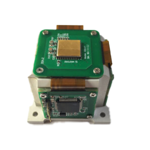
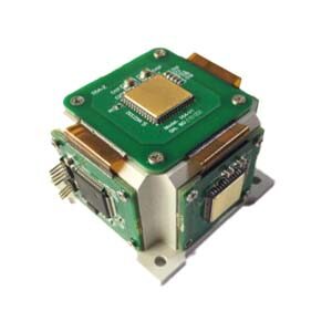
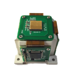
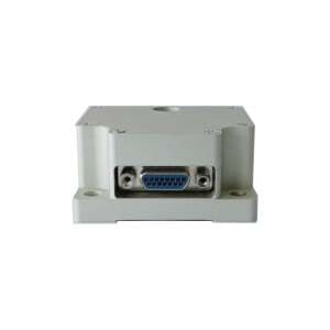
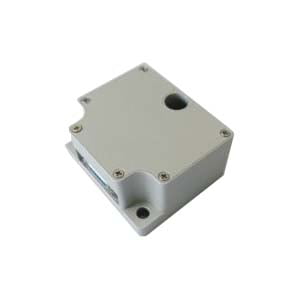
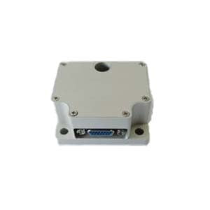
Inertial Measurement Unit (IMU) A device used to measure speed, direction, and gravity. Early on, IMU consisted of two sensors, accelerometer and gyroscope. Accelerometers measure inertial acceleration, while gyroscopes measure angular rotation. These sensors have three degrees of freedom and can measure from three axes. Later, IMUs introduced magnetometers, which measured the direction of magnetic forces and helped improve gyroscope readings. IMU applications include various fields such as tracking, navigation and robotics. IMU helps us determine the instantaneous position, speed, orientation and direction of movement of an object or vehicle.
1.IMU type
1.1 IMU with two sensors - This type of IMU consists of accelerometer and gyroscope. Each sensor has two or three degrees of freedom defined for the x, y, and z axes, and two sensors combined add four or six degrees of freedom. The acceleration values measured by the accelerometer and the angular velocity measured by the gyroscope are recorded separately, while the angles measured using both sensors are calibrated to obtain accurate data. If such an IMU is present around the sensor, it will not be disturbed by external magnetic fields. Its accuracy suffers due to sensor noise and gyroscope drift issues. ·
1.2 IMU with three sensors - This type of IMU consists of accelerometer, gyroscope and magnetometer. All sensors have 3 degrees of freedom, corresponding to 3 different axes, for a total of 9 degrees of freedom. The magnetometer measures yaw rotation (that is, rotation about the vertical axis) and is calibrated against gyroscope data to account for drift. It is mainly used for dynamic orientation calculation when the drift error is small. If the IMU is present inside a magnetic field, its measurements may be affected because it uses a magnetometer.
2.IMU working guidelines
2.1 Accelerometer
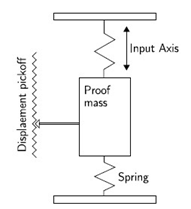
There are many types of accelerometers, and mechanical accelerometers and piezoelectric accelerometers are commonly used in IMU technology. Mechanical accelerometers consist of a spring-suspended mass. Measures the displacement of the mass, providing a signal proportional to the force F acting on the mass along the input axis. Calculate the acceleration acting on the device using Newton's second law, F = ma.
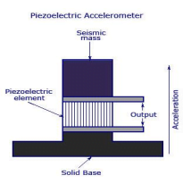
Piezoelectric accelerometers work on the principle of the piezoelectric effect, which is the ability of a material to become electrically polarized when subjected to mechanical stress. PE accelerometers use a PE element with a load mass (seismic mass) attached to form a 1 DOF mass spring system. The system makes one for each direction (left and right, front and back, and up and down in a three-axis accelerometer). Transient changes in stress on the PE element produce a charge at the output terminals of the accelerometer that is proportional to the applied acceleration.
2.2 Gyroscope
Likewise, gyroscopes are also available in different types, but MEMS based gyroscopes (MEMS) are implemented in IMUs. MEMS (microelectromechanical systems) is a technology that uses micromachining technology to create miniaturized mechanical and electrical devices and structures, with sizes ranging from less than one micron to several millimeters.
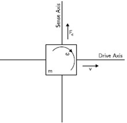
Gyroscopes use the Coriolis effect, which states that in a reference frame rotating at angular velocity w, a mass m moving with velocity v experiences a force Fc = −2m(w× v). MEMS gyroscopes contain vibrating elements such as vibrating wheels and tuning fork gyroscopes to measure the Coriolis effect. The simplest geometry consists of a single mass driven at a specific speed to vibrate along the drive axis, and when an external angular rotation (secondary rotation) is applied, secondary vibrations are induced along the vertical axis due to the Coriolis force. The angular velocity can be calculated by measuring this secondary rotation.
2.3 Magnetometer
About 90% of magnetometers work using the Hall effect. The principle of the Hall effect states that when a current-carrying conductor is placed in a magnetic field, a voltage will be generated perpendicular to the direction of the magnetic field and the direction of the current.
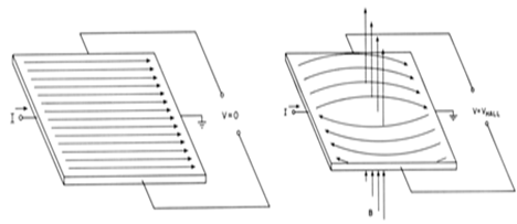
When a constant current flows through a piece of semiconductor material, in the absence of a magnetic field, there is no potential difference at the output. However, when a vertical magnetic field is present, the direction of the current flow is disturbed, creating a potential difference between the output terminals. This voltage is called Hall voltage. Keeping the input current constant, measure the magnetic field strength proportional to the Hall voltage.
3.How to calibrate IMU during operation
IMUs combine input data from multiple different sensors to accurately measure motion. To obtain accurate values, the sensor must be calibrated rather than using raw data. Calibration parameters can be stored in the IMU's memory and automatically reflected in the result data. Calibration can also be accomplished by using a magnetometer, which reduces directional drift (errors that accumulate over time). Some devices use proprietary sensor fusion algorithms to combine magnetometer and gyroscope data to determine the device's orientation relative to a global reference frame. Sensor fusion is the process of using signals from two or more types of sensors to update or maintain the state of a system (direction, velocity, and displacement). Sensor fusion algorithms maintain this state using IMU accelerometer and gyroscope signals as well as signals from other sensors (such as magnetometers) or sensor systems. The most popular technique for performing sensor fusion is the Kalman filter.
The Kalman filter is an optimization algorithm for estimating the state of systems with noise and uncertainty. This filter accepts noisy imprecise measurements and it is able to estimate the current state and even predict future states with good accuracy. The Kalman filter uses all sensor axis contributions within the IMU to estimate the direction angle, thereby minimizing drift.
4 .Conclusion
In application fields, IMU is used in various tracking systems such as unmanned navigation systems, vibration control, and measurement. In unmanned navigation systems (drone, aircraft), the navigation-level IMU developed by ERICCO can independently seek north, such as ER-MIMU01 and ER-MIMU-05. Their advantages are: light weight, small size, low Cost, high performance, due to these characteristics they can be mass produced, and equipped with X, Y, Z three-axis precision gyroscope, X, Y, Z three-axis accelerometer, high resolution, can output X, Y, The original hexadecimal complement data of Z three-axis gyroscope and accelerometer (including gyroscope hexadecimal complement value temperature, angle, accelerometer hexadecimal temperature, acceleration hexadecimal complement value); It can also output floating-point dimensionless values of gyroscopes and accelerometers processed by low-level calculations. The angular velocity random walk in the gyroscope is less than 0.005, the paranoid stability is less than 0.01, and the accuracy is higher than that of other inertial navigation companies.
If you want to learn about or purchase an IMU, please contact our relevant personnel.
More Technical Questions
3.Differences between IMU, AHRS, VRU and INS
4.Difference between AHRS and IMU
5.IMU Based on MEMS Technology
6.Wide Application and Technical Development Trend of IMU Inertial Measurement Unit
Products in Article
