MEMS gyroscopes are more useful than traditional gyroscopes because they generally measure angular velocity and angular displacement. Angular velocity measurements are more useful because the angular displacement and velocity can be measured indirectly over time.
There are many techniques that can be used to detect the angular velocity of a MEMS gyroscope. These techniques often have one thing in common, that is, they use a vibrating block instead of a rotating block. The vibrating block resists changes in the axial direction of the vibration even if the structure connected to it is rotating. Therefore, the same rotation detection effect can be obtained by using vibration instead of full rotation, and full rotation is more difficult to achieve in MEMS devices.
The physical phenomenon behind MEMS gyroscopes is the Coriolis effect. This phenomenon occurs when an object moves in a linear direction in a rotating reference frame. Suppose you are standing on a rotating carousel that is rotating, and the location is marked as t1. If you decide to go straight out, you can appreciate the Coriolis effect.
Speed and acceleration vectors presented in the Coriolis effect.
According to physics, we know that any point on a carousel has an instantaneous velocity Ωr, where Ω is the rotational speed and r is the radius of the point on the rotating wood. So each blue velocity vector in figure 1 has an amplitude Ωr, and if you stand at any point, you will have the same tangential velocity. The red constant velocity vector represents the radial velocity and is the speed at which you go outside. As you get closer to the outside, your tangential speed will increase. This achieves a half-acceleration effect from the Coriolis effect, with a value equal to Ωv, where v represents the radial velocity.
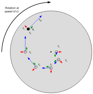
Figure 1. Velocity and acceleration vectors present in the Coriolis Effect
The second part of the Coriolis acceleration comes from the acceleration vector. If you look at the red velocity vectors at t1 and t2, you will notice that their amplitudes are the same, but they are in different directions. This change in direction of the velocity vector means that there must be tangential acceleration in the direction of the green vector. This acceleration is the other half of the Coriolis acceleration, which is also equal to Ωv. Therefore, if you add two independent acceleration vectors together, you can get 2Ωv. If your mass is m, this acceleration will apply 2Ωvm to you. This force produces a counterforce of the same magnitude and opposite direction on the carousel, with a value equal to –2 Ω vm. Since this is a negative value, the direction of the force is opposite to the direction of rotation.
If you are going back to the center of the carousel, then all mathematical calculations are the same, except that the red velocity vector now points inside, making them appear opposite signs. The final equation for your reaction at this point is –2 Ω (–v) m, or 2 Ω vm. So if you go inside, the magnitude of the reaction you produce on the carousel will remain the same, in the same direction as the direction of rotation.
To visually represent a MEMS gyroscope, a person can be replaced with a radially moving micro-vibration block and replace the carousel with any structure you wish to mount the gyroscope on.
The micro-block m will vibrate back and forth, thus producing a vertical Coriolis force of the same frequency. The magnitude of these forces is equal to ±2 Ωvm and is directly proportional to the angular velocity Ω of the overall system. These forces will cause the white portion of the component shown in Figure 2 to be pushed from one side to the other, and these displacements can be detected as changes in capacitance.
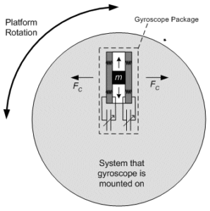
Figure 2. Implementation of a MEMS gyroscope
At this time, what the gyroscope needs is to use the relevant circuit to detect the oscillation of the capacitor, convert it to a voltage, and then rectify and output a DC voltage. The purpose of this circuit is to convert the rotational speed into a voltage. Some gyroscope manufacturers are integrating all of these functions into a single package, enabling a small, efficient but cost-effective solution. Some MEMS gyroscope manufacturers have adopted the simplest signal conditioning method in order to reduce the price of the product, so external circuits are needed to achieve signal adjustment and accurate measurement.
The main application areas of MEMS gyroscope
Industrial field:
In the field of petroleum and mining, mems gyroscope is widely used in coal mining and oil exploration. By using the internal vibration structure to determine the bit speed, and then determine the well inclination, orientation, tool face and other parameters, real-time monitoring of the well trajectory and bit position can be realized to ensure that the well depth reaches the predetermined position. Different from traditional sensors, MEMS gyroscopes have obvious advantages in drilling applications, MEMS gyroscopes are smaller, lower power consumption and lower cost; MEMS gyro inclinometer can obtain the measurement data in real time after the pump is stopped, which greatly improves the construction efficiency and reduces the construction cost. At the same time, compared to mechanical gyros, MEMS gyros can withstand extreme conditions such as downhole shock and vibration, do not need to be recalibrated during use, and consume less energy. ER-MG2-50/100, this gyroscope is very suitable for this field of application, it has a high performance MEMS gyro sensor with 0.01-0.02°/hr bias instability and 0.0025-0.005°/√hr Angular Random Walk,and is specially designed for north seeking, pointing, initial alignment in logging tools/gyro tools, mining/drilling equipment.
Aerospace field:
In the field of aerospace, mems gyroscopes are widely used in the attitude control system of aircraft. By measuring the angular velocity and Angle of the aircraft, the attitude information of the aircraft can be fed back in real time to help the aircraft maintain a stable flight state. At the same time, mems gyroscopes can also be used in the navigation system of the aircraft to provide accurate direction and position information to help the aircraft navigate and position.
Automotive navigation field:
In the field of automotive navigation, mems gyroscopes are used in vehicle navigation systems. By measuring the steering Angle and steering speed of the car, the mems gyroscope can monitor the driving state of the car in real time, helping the navigation system accurately calculate the position and direction of the vehicle. In urban environments, due to the instability of GPS signals, mems gyroscopes can provide reliable navigation AIDS and improve the accuracy and reliability of navigation systems.
If you want to get more details about MEMS gyroscope, pls visit https://www.ericcointernational.com/gyroscope/mems-gyroscope
More Technical Questions
1.What’s the advantages and disadvantages of MEMS gyroscope?
2.How accurate is MEMS gyroscope?
3.Where are MEMS Gyroscopes Used?
4.How to select MEMS gyroscope?
5.MEMS gyroscope VS FOG: What’s the difference between them?
6.How to Distinguish MEMS Accelerometer and MEMS Gyroscope Correctly?
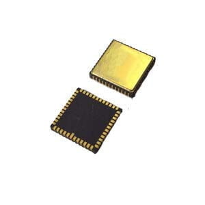
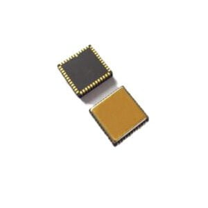
Products in Article

.jpg)

