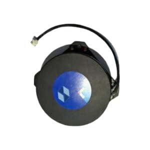
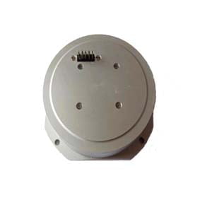
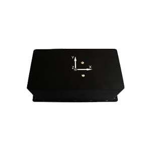
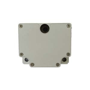
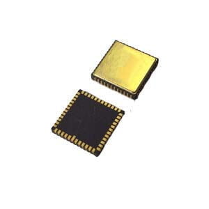
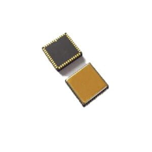
The fiber optic gyroscope is a sensitive element based on an optical fiber coil, and the light emitted by the laser diode propagates along the optical fiber in two directions. The difference in the light propagation path determines the angular displacement of the sensitive element.Fiber optic gyro is a fiber optic angular velocity sensor, which is the most promising one among all kinds of fiber optic sensors. Like ring laser gyro, fiber optic gyro has the advantages of no mechanical moving parts, no preheating time, insensitive acceleration, wide dynamic range, digital output and small size. In addition, fiber optic gyro also overcomes the fatal shortcomings of ring laser gyro such as high cost and blocking phenomenon.
1. Zero offset and zero drift
Zero bias is the output of the gyroscope when the input angular velocity is zero (ie the gyro is stationary), expressed by the equivalent input angular velocity corresponding to the average value of the output measured within a specified time, ideally the component of the earth's rotation angular velocity. Zero drift is the zero bias stability, which means that when the input angular rate is zero, the discrete degree of the gyroscope output around its zero bias mean is expressed by the equivalent input angular rate corresponding to the standard deviation of the output within a specified time. Zero drift is the most important and basic indicator to measure the accuracy of fiber optic gyroscope. The main factor producing zero drift is the non-reciprocal phase shift error introduced within the fiber coil by ambient temperature changes distributed along the fiber. Usually, in order to stabilize the zero drift, it is often necessary to perform temperature control or temperature compensation on the FOG. In addition, polarization will also have a certain impact on zero drift. In FOG, polarization filtering and polarization-maintaining fibers are often used to eliminate the effect of polarization on zero drift.
2.Scale factor
The scale factor is the ratio of the output of the gyroscope to the input angular rate. It can be represented by the slope of a specific straight line on the coordinate axis. It is an index reflecting the sensitivity of the gyroscope. Its stability and accuracy are an important indicator of the gyroscope. , which comprehensively reflects the testing and fitting accuracy of the FOG. The stability of the scale factor is dimensionless and is usually expressed in parts per million (ppm). The error of the scale factor mainly comes from the temperature change and the instability of the polarization state of the fiber.
3.Random walk coefficients
It is a technical index that characterizes the white noise of the angular velocity output in the fiber optic gyroscope. It reflects the uncertainty accumulated over time of the angular velocity integral output by the fiber optic gyroscope, so it can also be called angular random walk. The random walk coefficient reflects the development level of the gyroscope, and also reflects the minimum detectable angular rate of the gyroscope. This error mainly comes from random spontaneous emission of photons, noise and mechanical jitter introduced by photo detectors and digital circuits.
4.Threshold and Resolution
The threshold represents the minimum input rate that the FOG can sense. Resolution represents the smallest input rate increment that the gyroscope can sense at a specified input angular rate. Both threshold and resolution characterize the sensitivity of the fiber optic gyroscope.
5.Maximum input angular velocity
Represents the maximum value of the input rate in the forward and reverse directions of the gyroscope, and represents the dynamic range of the gyroscope, that is, the rate range that the fiber optic gyroscope can sense.
Features
Compared with electromechanical gyroscope or laser gyroscope, fiber optic gyroscope has the following characteristics:
(1) There are few parts, the instrument is firm and stable, and it has strong anti-shock and anti-acceleration ability;
(2) The wound fiber is longer, which improves the detection sensitivity and resolution by several orders of magnitude compared with the laser gyroscope;
(3) There are no mechanical transmission parts, there is no wear problem, so it has a long service life;
(4) It is easy to use the integrated optical circuit technology, the signal is stable, and the digital output can be directly used and connected with the computer interface;
(5) By changing the length of the optical fiber or the number of cyclic propagations of light in the coil, different precisions can be achieved and a wider dynamic range can be achieved;
(6) The propagation time of the coherent beam is short, so in principle, it can be started instantly without preheating;
(7) It can be used together with the ring laser gyroscope to form the sensors of various inertial navigation systems, especially the sensors of the strapdown inertial navigation system;
(8) Simple structure, low price, small size and light weight.
More Technical Questions
1.What Performance is the FOG sensor in FOG North Finder
2.MEMS and FOG: How Should you Choose Inertial Navigation System?
3.Does MEMS Replace FOG Technology?
4.Do You Know the FOG North Finder?
5.What is the System Structure of FOG North Finder
6.How to Use Acquisition Software of MEMS North Seeker
Products in Article
