


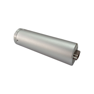
Low Power Inertial Measurement Unit
Introduction
An inertial measurement unit (IMU) is a device that measures the three-axis angular velocity and acceleration of an object. With the development of science and technology, MEMS IMUs are increasingly widely used in fields such as petroleum and mining, injecting new vitality into traditional industries. This is a high-performance product specifically designed for oil drilling and mining. Based on a three-axis integrated MEMS gyroscope and a three-axis accelerometer, the ER-MIMU-09B can measure linear acceleration and rotational angular velocity from three directions, and obtain the attitude, velocity, and displacement information of the carrier through calculation. It also incorporates a north-finding algorithm, autonomously determining true north without relying on an external geomagnetic reference, adapting to complex downhole environments.
Features
Mini diameter: 120mm x Φ30mm
Light weight: ≤150g
Temperature compensation: -40℃~ + 80℃
Products with wide voltage design: 6v~12v
For gyroscope tools
Trajectory measuring instruments
Mining-while-drilling equipment
Application
North seeking in logging tools/gyro tools
Pointing, steering and guiding in advanced mining/drilling equipment
Initial alignment in UAV launch systems
Direction pointing and tracking in satellite antenna, target tracking system
Guidance and navigation in navigation grade MEMS system
Orientating and positioning in railway train system
Precision platform attitude measuring and controls
Precision attitude, position measuring in navigation grade MEMS IMU/INS
North finding and positioning in land surveying/land mobile mapping system
Specifications
| ER-MIMU-09B | ||
| Item | Parameter | Unit |
| Gyro performance | ER-MIMU-09B | / |
| Range | 200 | deg/s |
| Scale Factor at 25°C | 40000 | LSB/deg/s |
| Scale Factor Repeatability (1σ) | <100 | ppm |
| Scale Factor VS Temperature (1σ) | 300 | ppm |
| Scale Factor Non-Linearity (1σ) | <300 | ppm |
| Bias Instability (1σ 25℃) | <0.02 | deg/hr |
| Bias stability (10s 1σ) | <0.1 | deg/hr |
| Angular Random Walk | <0.005 | °/√h |
| Bias Repeatability (1σ 25℃) | <0.1 | deg/hr |
| Accelerometer performance | ||
| Range | 30 | g |
| Bias Stability (10s 1σ) | <75 | ug |
| Bias Month Repeatability(1σ) | 100 | ug |
| Bias Temp Hysteresis | <1.5 | mg |
| Scale Factor Non-linearity | <500 | ppm |
| Scale Factor Month Repeatability | <30 | ppm |
| Scale Factor Temp Coefficient | 100 | ppm/℃ |
| Class II Non-linearity Coefficient | <100 | ug/g² |
| Scale Factor | 250000 | Lsb/g |
| Environment and power | ||
| Operate temperature | -40~+80 | ℃ |
| Storage temperature | -55~+105 | ℃ |
| Power supply | 6~12V DC | V |
| Power (Power supply 6) | 2 | W |
| Communication interface | RS-422 | / |
| Physical characteristics | ||
| Size | 120 x φ30 | mm |
| Weight | ≤150 | g |
Dimension

Product composition and working principle
The product is mainly composed of three-axis MEMS accelerometer and gyroscope. The working principle is as follows: the gyroscope and accelerometer data are collected by ARM microcontroller, three high-precision gyroscopes are collected by 1-channel digital interface SPI, and three accelerometers are collected by another 1-channel digital interface SPI. All sensors are calibrated and compensated in software after acquisition.
Product technical characteristics
a)The product is designed for miniaturization and low power consumption;
b)Products with wide voltage design;
Electrical interface
The MIMU inertial measurement unit uses J30J-15ZKN-J output. Electrical pin definitions are shown in Table 1
Table 1 Pin definition of MIMU high precision inertial measurement unit
| Pin number | Electrical characteristic | Signal direction | Remark |
| 1 | VCC | Power + | 6-12V |
| 2 | Retain, disable | ||
| 3 | GND | Power supply - | |
| 4 | Retain, disable | ||
| 5 | Retain, disable | ||
| 6 | RS422,TX+ | ||
| 7 | RS422,TX- | ||
| 8 | RS422,RXD+ | ||
| 9 | RS422,RXD- | ||
| 10 | Retain, disable | ||
| 11 | Retain, disable | ||
| 12 | Retain, disable | ||
| 13 | Retain, disable | ||
| 14 | Retain, disable | ||
| 15 | Retain, disable |
Communication protocol
RS-422 serial interface, default baud rate 921600bps, 8bit data bit, no check bit, 1bit stop bit, specific baud rate are shown in Table 1; The default data refresh rate is 400Hz.
Data output protocol
| Byte | Define | Note | Range | Units | |||
| 1~4 | Protocol Head | EB8055AA | / | / | |||
| 5~8 | X axis angular rate | int | -50~50 | -100~100 | -200~200 | Degree/s | |
| 9~12 | Y axis angular rate | int | -50~50 | -100~100 | -200~200 | Degree/s | |
| 13~16 | Z axis angular rate | int | -50~50 | -100~100 | -200~200 | Degree/s | |
| 17~20 | X axis accelerated speed | int | -30~+30 | -60~+60 | m/s^2 | ||
| 21~24 | Y axis accelerated speed | int | -30~+30 | -60~+60 | m/s^2 | ||
| 25~28 | Z axis accelerated speed | int | -30~+30 | -60~+60 | m/s^2 | ||
| 29~32 | IMU temperature | float | |||||
| 33 | Frame count | unsigned char | 1~255 | ||||
| 34 | Sum | unsigned char | Byte 3~60 summation | ||||
Test interface operation description
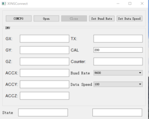
The user installs the test interface on the computer, as shown below.
Click the "Buad Rate" drop-down menu to select the desired baud Rate, and then click "Set Buad Rate" button to set the serial port baud rate. The setting takes effect only after the IMU is powered on again. Click the "Data Speed" drop-down menu, select the Data update rate of the IMU, and click the "Set Data Speed" button to set the setting. The setting will take effect only after the IMU is powered on again. Click "COMCFG" to configure the baud rate of RS422 serial port, which is the COM port required; Click the "Open" button to open the RS422 communication interface and power on the IMU. The Angle data of X,Y,Z gyro "GX,GY,GZ", the data of X,Y,Z accelerometer "ACCX,ACCY,ACCZ" will be displayed on the interface. The temperature data of IMU will be displayed in the "TX" box. Click "CAL" box to set the data update rate of the interface, which is consistent with the data update rate of the IMU. The "Counter" box displays the frame serial number for each frame of data..
Precautions for use
1)Installation error description
Internal orthogonal compensation has been carried out for the whole product. If the platform used by the product cannot guarantee the accuracy of the benchmark after installation, please compensate the installation error accordingly.
2)Installation and protection
When the product is installed, it should be tightly installed parallel to the base level of the carrier installation (the installation error with the base level should be less than 0.05°).
Because the product is a precision test instrument, although there is a shell protection, in order to protect the product damage, users should handle gently. The use and movement of the product should avoid falling, and be sure not to let the product and other components in the use of serious impact, to ensure the accuracy of the product datum requirements.
After sale
If there is any technical problem or failure in the use of the product, you can contact the corresponding technical personnel of our company.
Application Techniques
1.Do you know the core components that give precise control to automated equipment
2.High-performance IMU: A New Benchmark for Precise Measurement and Control
3.Industrial Versatile Tool: High Cost-Performance IMU Meets Diverse Needs
4.Flight safety secrets: The core role of high-precision IMUs in aviation
5.Revolutionizing drone navigation: How to redefine high performance and low cost
6.From flight control to fault diagnosis, how does IMU dominate drones?
More Products
 North-Seeking MEMS IMU
 High Accuracy North-Seeking MEMS IMU
 North Seeking Mems Imu For Gyro Tools
 North-seeking MEMS IMU
 Economical MEMS Gyroscope