


ER-MIMU-104 Low-cost Attitude Control MEMS IMU
Introduction
ER-MIMU-104 is a micromechanical technology (MEMS)-based inertial measurement unit (IMU). Built-in three-axis gyroscope and three-axis accelerometer to measure three-axis angular velocity and acceleration.
The ER-MIMU-104 uses a high-quality, reliable MEMS accelerometer and gyroscope. It can be used for attitude measurements. The product uses high-performance MEMS inertial devices, which have high reliability and high robustness, and can accurately measure the angular velocity and acceleration information of moving carriers in harsh environments.
Features
Three-axis digital gyroscope:
Dynamic measurement range:±400º/s;
Bias instability: 1º/h (Allan variance);
Angle random walk: 0.2º/√h.
Three-axis digital accelerometer:
Dynamic measurement range: 30g;
Bias instability: 10ug(Allan variance);
Ensure accuracy over the full temperature range (-40°C~80°C): Built-in high-performance temperature calibration and compensation algorithm;
Low power consumption: 2W
Communication interface: 1 SPI
Applied to service robots
Attitude control and health monitoring of energy equipment
Application
Industrial instrumentation attitude measurement
Robot attitude control
Indoor people tracking, navigation, and tracking
Platform stability and control
Pipeline Inspection, exploration & positioning
Specifications
| ER-MIMU-104 | |||
| Parameter | Test condition | ER-MIMU-104 | Unit |
| Gyroscope | |||
| Measuring range | ±400 | º/s | |
| Bias stability | 10s smoothing, 1σ | 5 | º/h |
| Bias instability | (1σ 25℃)
Allan variance |
3 | º/h |
| Random Walk | 0.25 | º/√h | |
| Bias Repeatability | (1σ 25℃) | 5 | º/h |
| Scale factor at 25°C | 20000 | LSB/°/s | |
| Scale factor non-linearity | 200 | ppm | |
| Bandwidth | 200 | Hz | |
| Accelerometer | |||
| Measuring range | ±30 | g | |
| Bias instability | Allan variance | 20 | ug |
| Bias stability | 10s smoothing, 1σ | 75 | ug |
| Bias temp coefficient | <20 | ug/℃ | |
| Bias Temp Hysteresis | <1 | mg | |
| Bias repeatability | 100 | ug | |
| Scale factor non-linearity | <3000 | ppm | |
| Scale factor month repeatability | <30 | ppm | |
| Bandwidth | 200 | Hz | |
| Communication Interface | |||
| 1 way SPI | Baud rate | <15 | MHz |
| Electrical specification | |||
| Voltage | 6~12 | V | |
| Power consumption | 2 | W | |
| Structural characteristics | |||
| Dimension | 47×44×14mm | ||
| Weight | 40 | g | |
| Operating environment | |||
| Operating temperature | -40~80 | ℃ | |
| Storage temperature | -55~105 | ℃ | |
Dimension

Product composition and working principle
The product is mainly composed of three-axis MEMS accelerometer and gyroscope. The working principle is as follows: the gyroscope and accelerometer data are collected by ARM microcontroller, three high-precision gyroscopes are collected by 1-channel digital interface SPI, and three accelerometers are collected by another 1-channel digital interface SPI. All sensors are calibrated and compensated in software after acquisition.
Product technical characteristics
a)The product is designed for miniaturization and low power consumption;
b)Products with wide voltage design.
Electrical interface
The MIMU inertial measurement unit uses MW12-03-G-D-130-112 output externally, and the mating connector is Samtec CLM-112-02-L-D. The electrical pin definitions are shown in Table 1.
Table 1 Pin definition of MIMU high precision inertial measurement unit
| Pin serial number | name | type | description |
| 10,11,12 | VDD | power supply | |
| 13,14,15 | GND | Power Ground | |
| 7 | DIO1 | I/O | Generic I/O, configurable |
| 9 | DIO2 | I/O | |
| 1 | DIO3 | I/O | |
| 2 | DIO4 | I/O | |
| 3 | SPI-CLK | input | The SPI defaults to slave mode |
| 4 | SPI-MISO | output | |
| 5 | SPI-MOSI | input | |
| 6 | SPI-CS | input | |
| 8 | RST | input | reposition |
| 16~24 | NC | spare | Manufacturer reserved |
Communication protocol
Data output protocol
| R/W | PAGE_ID | address | default | Register description |
| R/W | 0x00 | 0x00 | 0x00 | Page identifier |
| R | 0x00 | 0x0E | N/A | temperature |
| R | 0x00 | 0x10 | N/A | x axis gyroscope output, low word |
| R | 0x00 | 0x12 | N/A | x axis gyroscope output,high word |
| R | 0x00 | 0x14 | N/A | y axis gyroscope output, low word |
| R | 0x00 | 0x16 | N/A | y axis gyroscope output,high word |
| R | 0x00 | 0x18 | N/A | z axis gyroscope output, low word |
| R | 0x00 | 0x1A | N/A | z axis gyroscope output,high word |
| R | 0x00 | 0x1C | N/A | x axis accelerometer output, low word |
| R | 0x00 | 0x1E | N/A | x axis accelerometer output,high word |
| R | 0x00 | 0x20 | N/A | y axis accelerometer output, low word |
| R | 0x00 | 0x22 | N/A | y axis accelerometer output,high word |
| R | 0x00 | 0x24 | N/A | z axis accelerometer output, low word |
| R | 0x00 | 0x26 | N/A | z axis accelerometer output,high word |
Transform formulas
Current temperature =25+ TEMP_OUT* 0.00565
| X axis gyroscope for example | X_GYRO_OUT | X_GYRO_LOW |
| 1LSB=0.02°/S | The weight of the MSB is 0.01°/s, and the weight of the successors is half that of the previous one | |
| 0.02*X_GYRO_OUT | 0.01*MSB+0.005*....... |
YZ gyroscopes are calculated in a similar way to X-axis gyroscopes。
| X axis accelerometer for example | X_ACCL_OUT | X_ACCL_LOW |
| 1LSB=0.8mg | The weight of the MSB is 0.4mg, and the weight of the successors is half that of the previous one | |
| 0.8*X_ACCL_OUT | 0.4*MSB+0.2*....... |
YZ accelerometers are calculated in a similar way to X-axis accelerometers。
Note: For gyroscope, accelerometer fraction high 16bit, and low 16bit, the final result of addition is calculated separately
Test interface operation description
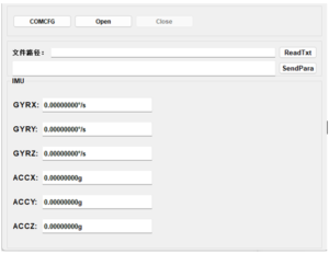
The user installs the test interface on the computer, open xInsConnect.exe,as shown below.
Click "COMCFG" to configure the baud rate, which is the COM port required; Click the "Open" button power on the IMU
Precautions for use
1)Installation error description
Internal orthogonal compensation has been carried out for the whole product. If the platform used by the product cannot guarantee the accuracy of the benchmark after installation, please compensate the installation error accordingly.
2) Installation and protection
When the product is installed, it should be tightly installed parallel to the base level of the carrier installation (the installation error with the base level should be less than 0.05°).
Because the product is a precision test instrument, although there is a shell protection, in order to protect the product damage, users should handle gently. The use and movement of the product should avoid falling, and be sure not to let the product and other components in the use of serious impact, to ensure the accuracy of the product datum requirements.
After sale
If there is any technical problem or failure in the use of the product, you can contact the corresponding technical personnel of our company.
Application Techniques
1.Do you know the core components that give precise control to automated equipment
2.High-performance IMU: A New Benchmark for Precise Measurement and Control
3.Industrial Versatile Tool: High Cost-Performance IMU Meets Diverse Needs
4.Flight safety secrets: The core role of high-precision IMUs in aviation
5.Revolutionizing drone navigation: How to redefine high performance and low cost
6.From flight control to fault diagnosis, how does IMU dominate drones?
More Products
 North-Seeking MEMS IMU
 High Accuracy North-Seeking MEMS IMU
 North Seeking Mems Imu For Gyro Tools
 North-seeking MEMS IMU
 Economical MEMS Gyroscope