

Main parameters of gyroscope
| Bias stability | ≤0.001°/h (100s Standard deviation) | |||||||
| Bias repeatability | ≤0.0003°/h | |||||||
| Angular random walk | ≤0.00015°/√h | |||||||
| Magnetic field sensitivity | ≤0.001°/h/Gs | |||||||
| Total error of scale factor | ≤2ppm(1σ) | |||||||
| Measuring range | -400~400°/s | |||||||
| Start time | ≤5s | |||||||
| Operating temperature | –40℃~+65℃ | |||||||
| Storage temperature | –55℃~+85℃ | |||||||
| Shock | 30g/11ms(half-sine), 75g/6ms(sine) | |||||||
| Vibration | 7.2g/5min (3 directions) | |||||||
| Frequency(Hz) | 10 | 100 | 200 | 300 | 600 | 1000 | 2000 | |
| Power(g2/Hz) | 0.1 | 0.4 | 0.1 | 0.02 | 0.005 | 0.00003 | -6dB | |
| Jitter frequency | 300Hz~420Hz, the jitter frequency of type A, type B and type C gyroscopes decreases successively, which should be avoided in the design of system structure | |||||||
| Low pressure | Altitude 5000m | |||||||
| MTBF | 15000h | |||||||
| Storage life | 15a | |||||||
| Size | (167±1)mm×(151±1)mm×(58±1)mm | |||||||
| Weight | 2.90±0.1kg | |||||||
| Power consumption | ≤4W | |||||||
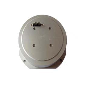
Mechanical interface

Figure 1 Shape and mounting dimensions of gyroscope
Mass Center

Figure 2 Mass Center for gyroscope
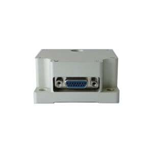
Electrical interface
The electrical interface adopts J30J-37ZK socket, as defined in the following table.
Table 1 Interface definition
| Node number | Name | Description |
| 9;27 | BTTL | Square wave output signal 2, TTL level, for phase detection |
| 10;28 | GND | Signal ground |
| 11;29 | ATTL | Square wave output signal 1, TTL level, for phase detection |
| 12 | PT1000-1 | Platinum resistance 1 |
| 30 | PT1000-2 | Platinum resistance 2 |
| 13 | PT1000-3 | Platinum resistance 3 |
| 31 | PT1000-4 | Platinum resistance 4 |
| 14;32 | PT1000-COM | 4 platinum resistance common ground |
| 15;33 | GND | ±5V Power supply ground, connected with the laser gyroscope housing |
| 16;34 | +5V | +5V Power supply |
| 17;35 | +15V | +15V Power supply |
| 18;36 | +15V_GND | +15V Power supply ground, Isolation from the laser gyroscope housing |
| 19;37 | -5V | -5V Power supply |
| Other pins | Manufacturer reserve |
Cautions for use
- Gyroscope should be avoided by impact, knock;
- Gyroscopes with the same jitter frequency should be avoided in the same inertial navigation equipment;
- Pay attention to the use of spring pad when installing the gyroscope. It is recommended to use M5 hex socket screw with grade 9 (including) or above, and the recommended torque value is 7NM.
Application Techniques
1.How does a ring laser gyroscope work?
2.What Is The Structure And Working Principle Of The Laser Gyroscope?
3.Laser Gyroscopes Shine In Many Fields Of Military And Civilian Use
4.Application of Laser Gyroscope
5.The Principle of Laser Gyroscope
6.China High Precision Laser Gyroscope
More Products