In this paper, the MEMS gyroscope technology is introduced into the urban underground pipeline measurement, using MEMS gyro to measure the triaxial acceleration and triaxial angular velocity, and using the measurement results to solve the underground pipeline mapping purpose.
In modern cities, the layout of underground pipelines is an important work, including communication, water supply, gas and electricity, and so on. It is necessary to choose the information measurement method and establish the underground pipeline measurement system. This project intends to use inertial control, remote sensing and other methods to build an underground pipeline mapping and management model based on information fusion, and an underground pipeline mapping model based on information fusion to provide technical support for improving the mapping level of urban underground pipelines. The infrared and CT scanning and measurement of the pipeline are carried out, and the real-time monitoring of the pipeline is realized by the mode of click transmission. A set of power sensing system for urban underground pipeline measurement is established and analyzed.
MEMS gyroscope
Different from the traditional mechanical gyroscope, MEMS gyroscope is an inertial angular rate sensor based on the Coriolis effect, which does not need bearings inside, no rotating parts, and adopts an all-solid-state device, which is characterized by small size, intelligence, low price, high reliability, resistance to large overload impact, low power consumption and long working life. The MEMS gyro mapping device used in this paper is mainly divided into three parts, namely: The Ericco Inertial System measurement unit used by the odometer wheel group, the main body of the plotting device, and the support wheel group is a small inertial measurement unit ER-MIMU-07, which weighs less than 70g, has a gyro measurement range of ±400°/s, and zero bias instability of 0.3°/h. The high performance MEMS gyro ER-MG-067 is used in the IMU, which has zero bias instability of 0.3°/h and angular velocity random walk of 0.125 °/√hr. In order to ensure the reliable connection and convenient disassembly of the wheel group, the screw connection method and the wheel group replacement method are selected to meet the measurement requirements of underground pipelines. The structure of MEMS gyro sensor is shown in Figure 1.

Figure 1 Structure of MEMS gyroscope
System structure based on MEMS gyroscope
The underground pipeline mapping system uses MEMS gyroscope to collect relevant data, and then processes the collected data through pipeline mapping to measure the pipeline trajectory.
1. Main structure
The modular method ensures convenient maintenance of the equipment by simplifying the assembly process. The sealing and waterproof treatment of the mechanical connection parts and the selection of screw connection ensure the waterproof ability of the measuring equipment. The measuring device has a body of 60mm and a length of 435mm, on which there is a smooth coating and an antioxidant coating. At one end of the measuring device is the control panel, which is installed with the data interface, switches and work indicators, and at the other end, is the replaceable battery box, and the MEMS gyro is installed with two 12 V lithium batteries.
2. Wheel structure
The wheel group of underground pipeline mapping is composed of threaded shaft, support rod, roller, U-bracket, limit nut and bearing, and the two sealed bearings support the roller together to ensure the smooth operation of the roller. By adjusting the limit nuts, the diameter of the wheel set can be adjusted within a small amplitude, making it suitable for various calibers. In addition, the odometer assembly also assembled an odometer data transmission interface connected to the body, the structure has high waterproof performance.
Design and realization of underground pipeline mapping system
Firstly, the data acquisition module, data reading module, data storage module and switch module are initialized. During the data transmission process of MEMS gyros, the acquisition module is started and the collected data is stored in the FIFO queue. When the FIFO queue data is excessive, the data needs to be sent to the SD card, and the above operation is continued to transmit data to the SD card. Until the device is powered off.
First, the data acquisition module. The data collected includes odometer data, MEMS gyroscope data, which is sent out in 422 level form at a baud rate of 921600bps. In the process of collecting data at a high rate, this method is very efficient and can ensure the real-time acquisition of data. However, due to the large amount of data obtained at a time, the CPU is occupied, and the data that will be transferred to the SD card will be disturbed. Therefore, using serial DMA to receive data can prevent the impact on memory.
The second part is data storage. RS422 is used to complete DMA and serial communication, and the information obtained by the serial interface from the MEMS gyro is transmitted to the bus through DMA until all the data is received, then the serial idle terminal will be activated and all the data will be stored in BUF. Mile data is obtained from RS422, continuously accumulating the number of pulses triggered. The data collected by the two sensors is fused and stored in the FIFO, and the FIFO data is transferred to the SD card. Figure 2 shows the data storage process.
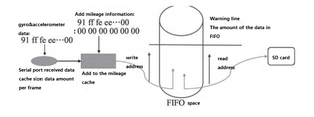
Figure 2 Data storage process
Again, the data read module. The core part of this module is to read SD card through USB interface. After the test, it is connected to PC through USB interface to realize real-time access to SD card and read out the internal information of SD card. In order to reduce power consumption, the design is in a non-working state during the test. After the test, the power supply is provided by the USB power supply on the computer, and the access to the SD card is realized through the PC.
Conclusion
Urban underground pipeline mapping equipment based on MEMS gyroscope is used to map the track of the pipeline by walking in the pipeline with the map equipment carried by the active equipment. This paper also introduces the MEMS IMU from Ericco Inertial System.
If you are interested in learning more about MEMS gyro, please contact us.
More Technical Questions
1.Integrated method of three-axis MEMS gyroscope
2.Development history of MEMS gyroscope
3.MEMS gyroscope processing technology
4.Research on driving mode of MEMS gyroscope
5.Stochastic error modeling method of MEMS gyroscope
6.Signal Denoising Principle And Evaluation Index of MEMS Gyroscope
Products in Article
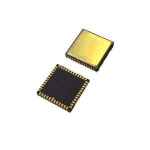
High precison MEMS Gyroscope
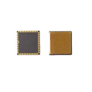
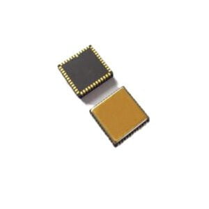
High Precision Stable-Control MEMS IMU

