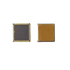
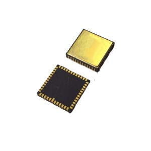
MEMS gyroscope is an inertial sensor used to measure angular rate or attitude angle. Because of its small size, low power consumption, easy mass production, low cost, it has been paid attention to and widely used in many industries. In recent years, MEMS technology has been developing rapidly, its performance is becoming more and more excellent, and the technology is becoming more and more perfect. We can judge the performance of MEMS gyroscope according to many influencing factors, damping is one of them. This paper aims to analyze the influence of damping on MEMS gyro, and introduces the concept and function of damping, classification and damping model.
Concept and function of damping in MEMS gyroscope
Damping is a method of limiting vibration, which is the dissipation of vibration energy over time and distance in solid media and structures. Similar to the absorption of sound in air, damping occurs whenever there is any type of friction, reducing motion and dispersing energy. The damping capacity of each material is called its loss factor, which represents the ratio between the energy dissipated during each cycle and the energy remaining in the system. Many people confuse damping with friction, which is a dissipative force acting on a system. Friction can cause or be a factor in damping, but friction and damping are not the same thing.
Damping is an effect within or on an oscillating system that has the effect of reducing or preventing its oscillation. In MEMS gyro, the damping coefficient and quality factor of its core structure are important factors affecting the dynamic response and performance of the gyro.
In simple terms, this is what happens with door or drawer springs, where damping prevents shock when opened or closed, thus protecting them and protecting the system.
Classification of damping in MEMS gyroscope
The damping of MEMS gyro core structure is mainly composed of the following two aspects:
- Structural damping: it comes from inside the material of the mechanical structure of the watch movement and is mainly affected by the material characteristics and structural dimensional characteristics.
- Gas damping: from inside the gyro chip package.
The structure damping of MEMS gyro is much less than that of gas under normal temperature and pressure, so the structure of gyro core is mainly determined by gas damping. Due to the Brownian motion of the gas molecules inside the chip package, the output signal of the gyroscope will contain a lot of random noise, so most of the current high-performance MEMS gyroscopes are designed in high vacuum package. However, due to the high technical level and certain leakage rate for MEMS gyro to achieve high vacuum packaging, non-vacuum packaging is still used for some applications that require long-term storage and require reliable and stable performance. The gas damping coefficient inside the gyro chip package is not only related to the characteristic parameters of the gas state, such as temperature, pressure, etc., but also depends on the way of gas flow and the geometry characteristics of the watch core structure. Therefore, gas damping becomes a factor that we need to focus on analysis.
According to the different ways of relative movement between the gas fluid and the watch movement structure, gas damping can be divided into::
- Synovial damping
- Pressure film damping
The following is a modeling analysis of these two dampers.
Modeling analysis of damping in MEMS gyroscope
1. Synovial damping
Synovial damping is the damping caused by the relative parallel movement of the mass plate along the substrate, which makes the gas flow move along the shear direction. When the parallel motion is relatively slow, the synovial damping model is Couette flow damping model, as shown in Figure 1.
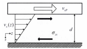
Figure 1 Couette flow damping model
The calculation formula of Couette's flow damping model is:
![]()
Where d is the vertical distance between the moving mass plate and the substrate, A is the area under damping force of the moving mass plate, and η is the coefficient of gas viscosity.
However, when the relative motion is relatively fast, that is, when the vibration frequency of MEMS gyro reaches tens of Khz, the inertial fluid part in the original model cannot be ignored. In this case, Stokes flow damping model should be adopted to analyze the synovial damping, as shown in Figure 2.
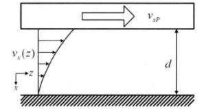
Figure 2 Stokes flow damping model
The damping model of Stokes flow is calculated as follows:

Among them, ω is the vibration frequency, ρ is the air density, and the standard value at room temperature and pressure is 1.16×10⁻¹⁸kg/(μm3). δ is the penetration depth, which represents how fast or slow the air flow velocity changes with the increasing displacement in the z direction, as shown by the following formula:
![]()
The Stokes flow model given by the formula is established under the condition that the gas flow is a pure viscous flow (i.e. low pressure value), while the Stokes flow damping model under general conditions cannot be analytically solved by the previous simple approximation. For the damping under this general condition, Stokes equation is usually combined with finite element simulation to establish a numerical solution model to solve and calculate the damping coefficient.
2. Pressure film damping
Pressure film damping is the damping generated by the gas flow compression caused by the mass plate moving along the normal direction of the substrate, as shown in Figure 3.
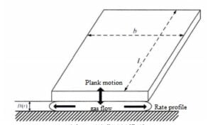
Figure 3 Pressure film damping model
The pressure film damping model can be derived from the viscous fluid theory and Reynolds equation, and the boundary conditions of the model are affected by the characteristic size of the gas fluid.
When the plate length L> plate width b meets the plate size condition, the pressure film damping can be approximated as:
![]()
When the size condition is a rectangular plate, the pressure film damping can be approximated as:
![]()
According to the structure of MEMS line vibration gyro and the above-mentioned damping characteristics, the damping generated by the drive and detection motion between the comb-capacitor can be analyzed using Stokes current damping model, and the damping of the relative motion between the side wall of the cantilever beam and the side wall of the detection mass block should be calculated according to the compression film damping. The damping generated by the relative parallel motion between the detection mass and the core substrate should be Couette flow damping. The gas damping generated by the relative movement of different parts of the watch core structure is shown in the following table.
| Movement structure | Damping model |
| Drive and detect combs | Stokes flow damping |
| Cantilever beam side wall and proof mass side wall | Pressure film damping |
| Detection mass block and watch core substrate | Couette flow damping |
Conclusion
From the above analysis, it can be seen that the gas damping of the gyro core is mainly affected by the geometrical characteristics of the core structure and the characteristics of the gas flow around the core structure. When the geometric characteristics of the design core structure remain unchanged, the gas damping is mainly affected by the ambient temperature and pressure. When the gas pressure is low (vacuum state), the change of ambient temperature has little influence on the gas damping. When the gas pressure is large (normal pressure state), the change of ambient temperature has a greater influence on the gas damping. Therefore, for MEMS gyroscope under normal pressure or low vacuum package conditions, its damping coefficient is more sensitive to the change of ambient temperature.
This paper analyzes the influence of damping on MEMS gyroscope. In order to cope with many influencing factors, Ericco, as a manufacturer of MEMS gyroscope, adopts a strict calibration method to deal with the errors caused by various factors, such as vacuum ceramic packaging. Therefore, Ericco's MEMS gyroscopes have excellent performance, such as ER-MG2-068, with zero bias instability <0.3°/hr and angular random walk <0.125°/√hr.
If you are interested in other MEMS gyro knowledge, please click on the related articles and products below to learn.
More Technical Questions
1.Error Analysis of MEMS Gyroscope
2.Noise Analysis and Solutions of MEMS Gyroscope
3.What’s the north-seeking principle of MEMS gyroscope?
4.The materials and structure of MEMS gyroscope
5.Wafer-level vacuum packaging of MEMS gyroscope chips
6.How does MEMS gyroscope work in harsh high temperature environment?
Products in Article
.jpg)
