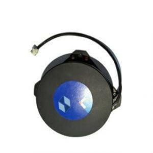
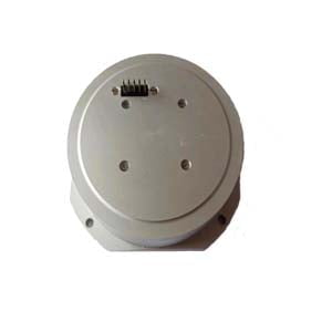
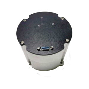
FOG gyro, as a new high-precision angular rate measuring instrument, has many advantages such as small size, high reliability and long life, and has been widely used in various industries such as military, commercial and civilian, and has a huge development space. However, when the operating temperature changes, the output signal will drift phenomenon, so that the measurement accuracy is greatly disturbed, and the application range is severely limited. Therefore, it is one of the difficult problems that must be solved to study the drift rule of fiber optic gyroscope and make error compensation to improve the applicability of fiber optic gyroscope in different temperature environments. At present, the output drift caused by temperature change is suppressed mainly from three aspects: hardware temperature control equipment, software modeling compensation and changing the mechanism structure of fiber optic gyroscope. Adding a local temperature control system in the fiber optic gyroscope can effectively compensate the real-time temperature error of the fiber optic gyroscope, but its volume and weight will also increase, which is inconsistent with the development trend of the miniaturization of the fiber optic gyroscope. The four-pole wraparound method is used to ensure that the influence of temperature on the optical coil is symmetrical, and reduce the non-reciprocal interference of temperature, so as to suppress the temperature drift of the fiber optic gyroscope, but the residual temperature drift will still have a great influence on the angular rate detected by the gyroscope. Therefore, improving the mechanism structure of fiber optic gyroscope is not the best choice to suppress temperature drift. Through software modeling compensation, all kinds of gyros can achieve better compensation effect, no space, low cost, so it has been widely used in practical engineering. We propose a temperature compensation model based on temperature and temperature change rate, which can be used to compensate the output drift of fiber optic gyro.
1 Temperature effect mechanism of FOG Gyro
The fiber optic gyroscope is an optical gyroscope based on the Sagnac effect. It consists of a light source, a photodetector, a beam splitter and an optical fiber coil. Temperature affects the precision of the fiber optic gyroscope by affecting the performance of the components inside.
Fiber optic coil is the core component of fiber optic gyroscope. Sagnac effect occurs when the fiber optic coil rotates relative to the inertial space. The structural reciprocity of fiber optic gyroscope can ensure that the transmission characteristics of a pair of light transmitted in the opposite direction will not be different due to the influence of its structure. However, the asymmetric temperature disturbance will change the reciprocity of the fiber optic gyroscope to some extent. Unless the temperature disturbance point is in the middle of the fiber ring, the phase difference will be generated when the light wave passes through the fiber ring at different times. The small phase error is easily superimposed on the phase difference accumulated by Sagnac effect, which seriously affects the output performance of the fiber optic gyroscope.
The optical fiber coil of a fiber optic gyroscope outputs interference optical signals, which need to be amplified by photoelectric sensors and converted into electrical signals that are easy to measure. As a photoelectric sensor with high detection sensitivity and reliability, the performance of the photodetector directly determines the quality of the measured voltage signal. The change of ambient temperature will make the photodetector produce a lot of noise, and the photodetector will produce a special current that increases with the increase of temperature when there is no light. The resistance value of the photodetector load resistance is also affected by temperature.
The interference light in fiber optic gyroscope is generated by the light source, and the temperature performance of the light source is related to the accuracy of Sagnac phase shift. The light source has different output power rate, mean wavelength and spectral width at different temperatures, and these three parameters determine the change of the output signal of the fiber optic gyroscope.
2 Modeling analysis of FOG Gyro
2.1 Temperature experiment and temperature characteristic analysis
It is difficult to summarize the temperature drift model by physical formula. It is a feasible measure to determine the model structure and parameters by system identification method. Firstly, the temperature and gyro output data are obtained through temperature experiment, and then the temperature compensation model based on polynomial fitting is determined, and the least squares method is used
The coefficients of the model are estimated. Temperature test selected 0℃~20℃, -40℃~-20℃, 40℃
In the three temperature zones of ° C~60°C, the temperature box is set as the initial value, and the fiber optic gyroscope is kept warm in the temperature box for 4h. When the temperature of the gyroscope is the same as the temperature of the temperature box, the fiber optic gyroscope is started and the temperature box is raised and cooled at a change rate of 5°C/h, and the temperature and the output data of the gyroscope are recorded.
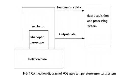
Figure 1 shows the connection diagram of the test equipment. The temperature box error used in the test is ± 0.5 ℃, the scale factor value of the fiber optic gyroscope is 650, and the temperature sensor is located on the fiber optic coil of the fiber optic gyroscope to measure the temperature change inside the gyroscope. The sampling interval is set at 1s. The experiment recorded the gyro output data in the three directions of X, Y and Z, three axes
They are independent of each other and have no connection between their outputs. The gyro output data usually contains a lot of high-frequency noise, so it is easier to identify the trend of gyro output with temperature change. When analyzing the gyro output data, it is smoothen for 100s.
The temperature change rate is approximately expressed as △T/ △t = T (t+60) - T (t), where the single position is ℃ / min, where T is temperature degree and t is time. The following takes the X-axis as an example to analyze the output of the fiber optic gyroscope
2 is the internal temperature, temperature change rate and gyroscope of the fiber optic gyroscope in three temperature segments (temperature segment 1, temperature segment 2 and temperature segment 3 are 0 ° C ~ 20 ° C, -40 ° C ~ -20 ° C, 40 ° C ~ 60 ° C in order)
Output change curve.
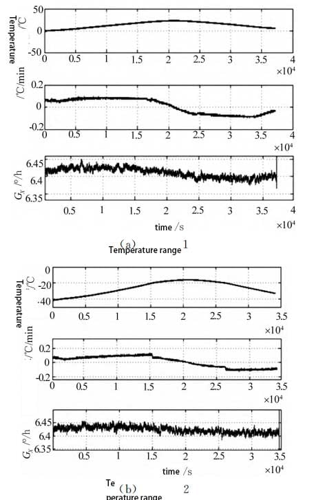
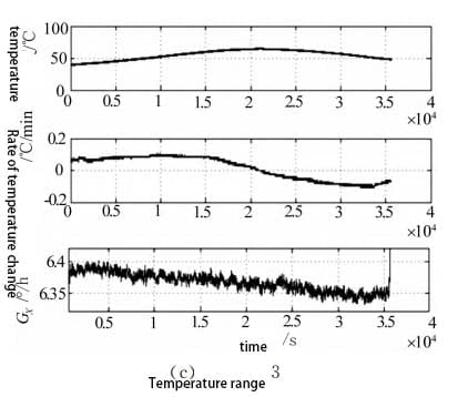
By comparing the output curves of the gyro with the temperature, it is found that the output of the gyro oscillates obviously with the change of temperature. By comparing the curve of temperature change rate and the output curve of gyro, it is found that the output curve of tourbolla and the curve of temperature change rate show the same rising or falling trend at the same time, and their shapes are similar. It can be seen that the temperature drift of tourbillon is closely related to the internal temperature and temperature change rate of the optical fiber gyro, so these two factors must be considered in the temperature compensation model.
2.2 Temperature drift modeling and compensation scheme
The method of polynomial fitting is often used to establish the temperature compensation model of fiber optic gyro in engineering. When the polynomial regression model is used to compensate the temperature drift of fiber optic gyroscope, the influence of temperature and temperature change rate on the compensation effect is analyzed. Generally speaking, the higher the order of the multi-term model, the better the degree of fitting and the higher the compensation accuracy, but the calculation amount of parameter estimation is also larger, and the real-time performance of the system is difficult to meet the requirements, which is not conducive to the application of engineering. Overall consideration, this paper takes the model order as 3.
1) Compensation effect based on temperature factor
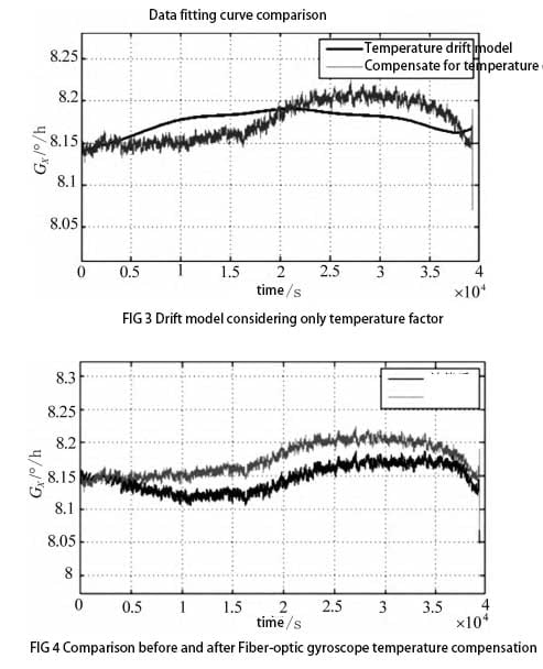
In the model, only the influence of temperature factors on the output of the gyroscope is considered, and there are the following compensation models:

In the formula, Lout is the output of tourbilla; L0 is the initial value of the gyro output (the average value of the output in the first 5 minutes after starting the tourtuo); T0 is the initial value of the gyroscope temperature (the average temperature of the first 1min after the gyroscope is started); T is the temperature on the gyro fiber coil; ai and bj are the coefficients of the polynomial model. Considering that the position of the gyroscope relative to the inertial space is not exactly the same during each measurement, the base value of the gyroscope output is different, and L0 is introduced. Considering the influence of ambient temperature on gyro output, T0 is introduced. Matlab was used for data fitting and coefficient calculation. The simulation results are shown in FIG. 3 and FIG. 4. It can be seen that the overlap between the gyro temperature drift model curve and the original gyro output curve is very low. After the data is smoothed for 100s, the compensated zero bias stability is 0.0200 ° / h.
2) Compensation effect based on temperature change rate
Considering the drift error caused by the temperature change rate to compensate, the following compensation model can be obtained:

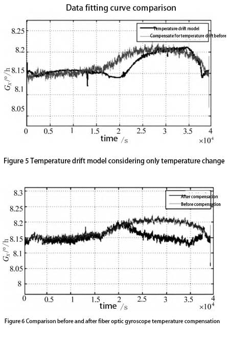
Where ck is the coefficient of the polynomial model. The simulation results are shown in Figure 5 and Figure 6, and only temperature factors are considered
Compared with prime time, the curve fitting degree of gyro temperature drift model is significantly improved. The zero bias stability after compensation is 0.0163 ° / h, and the dispersion degree of gyro output relative to its mean value is significantly reduced.
3) Comprehensive compensation effect based on temperature and temperature change rate
Temperature drift is compensated by combining temperature and temperature change rate. The compensation model is:

The simulation results are shown in FIG. 7 and FIG. 8. Both the temperature drift model curve and the compensated gyro output curve can reach the ideal degree of fitting, and the compensated gyro zero bias stability is 0.0055 ° / h. The influence of modeling based on various temperature factors on the zero-bias stability of fiber optic gyroscope is shown in Table 1.
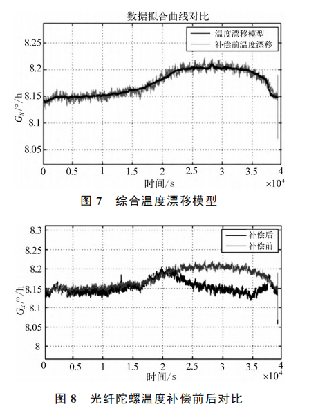
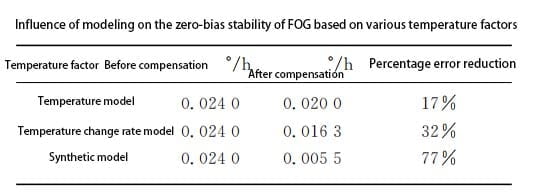
It can be seen from Table 1 that when the influence of temperature and temperature change rate is considered comprehensively, the error reduction percentage before and after FOG gyro temperature drift compensation is significantly increased, reaching 77%, and the zero bias stability is reduced by a number of degrees. It can be seen from the compensation results that the comprehensive compensation model has the best compensation effect.
2.3 Experimental analysis of temperature compensation
0 ° C ~ 20 ° C, -40 ° C ~ -20 ° C and 40 ° C ~ 60 ° C are recorded as temperature segments 1, 2 and 3, respectively. The same fiber optic gyroscope has different output drift in each temperature range, so it is necessary to compensate the output error of each temperature range. The following model is used for compensation, and the model parameters can be obtained by MATLAB parameter estimation as follows
Table 2 shows this.

The fitting parameters of the three temperature intervals were respectively brought into the model, and the gyro compensation effect was shown in Figure 9.
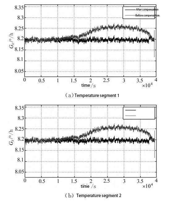
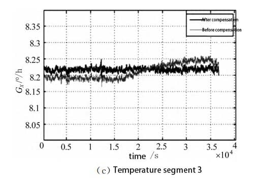
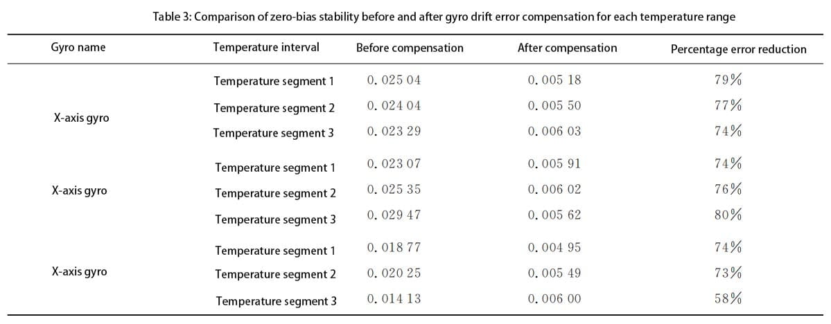
As can be seen from FIG. 9, temperature compensation for the fitting parameters of the error model in each temperature interval can obtain better compensation results. After compensation, the output drift of the fiber optic gyro is effectively improved, and the output stability of the gyro is improved. Compared with the output curve before compensation, the oscillation amplitude of the output curve after compensation is significantly suppressed, the curve is more flat, and the output drift is effectively improved. The zero-bias stability pairs before and after compensation are shown in Table 3. By using models with different parameters for error correction, a good compensation effect can be achieved for the temperature drift of the same fiber optic gyro in different temperature ranges and different FOG gyro in the same temperature ranges. After compensation, the output errors of X, Y and Z axis fiber optic gyro in the three temperature ranges can be reduced by about 75%, and the output accuracy is significantly improved. It is proved that the compensation method of piecewise fitting model parameters has certain practicability and effectiveness.
3. Summary
Based on the analysis of the temperature effect mechanism of FOG gyro and the output data of fiber optic gyroscope at different temperatures, we propose a three-order zero drift temperature compensation model which takes into account the current temperature, the difference between the current and the initial temperature and the temperature change rate. The experiment shows that the temperature drift model has a good compensation effect on the output signal of the gyro, greatly improves the output accuracy of the gyro, and solves the problem of temperature drift often encountered in engineering. Ericco's ER-FOG-50, ER-FOG-70 can be used to improve the output accuracy of the gyroscope in the above way. However, there are still many shortcomings, the temperature history is not continuous, the sample space is not comprehensive, so it is necessary to further research the compensation of gyro temperature drift in the whole temperature range.
More Technical Questions
1.Analysis of Fiber Optic Gyroscope Output Signal
2.Research on miniaturization technology of fiber optic gyroscope
3.Application of fiber optic gyroscope in aviation field
4.Analysis of Temperature Drift Compensation Method for Fiber Optic Gyroscope
5. Processing and Analysis of Random Drift Error Based on Fiber Optic Gyroscope
6.Application of Fiber Optic Gyroscope in oil drilling field
Products in Article
