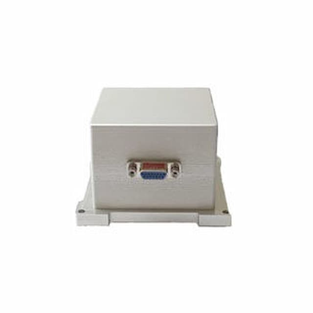
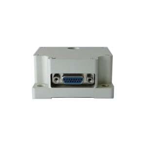
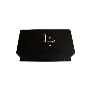
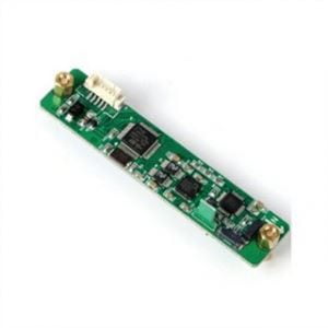
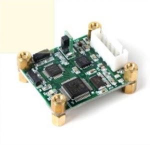
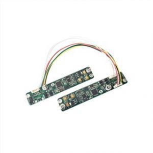
The mine direction alignment instrument is an instrument based on inertial technology, which has high accuracy and automation, and meets the measurement requirements in coal mine. However, its high cost limits its application and promotion in coal mine. Therefore, it is urgent to find a low cost drilling directional equipment that can meet the accuracy requirements. Based on the above practical problems in production, a new type of mine direction alignment instrument based on MEMS technology is developed and the prototype test is carried out to check the indicators, so as to meet the actual needs of the project.
1.Composition of directionalignment system
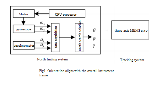
The orientation and direction alignment instrument is mainly composed of two parts: north seeking system and tracking system. The block diagram is shown in Figure 1. The north finding system is mainly used to measure the attitude data (inclination and azimuth) between the instrument and the geographical North Pole (true north direction) in the static case, that is, to determine the attitude reference with the true north direction. The tracking system is mainly used to measure the attitude measurement data which changes with time after the instrument seeks north. The measuring instrument is placed on the guide rail of the drilling rig parallel to the drill pipe, and the attitude (inclination and azimuth) of the drilling rig is adjusted according to the preset value, and the opening directional operation can be completed when the preset value is reached.
2.Working principle of direction alignment instrument
2.1 Principle of the north finding system:
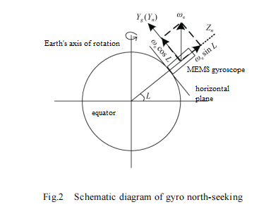
As shown in Figure 2, the direction of the Earth's rotation rate is parallel to the Earth's rotation axis. At the latitude L of the earth's surface, the angular velocity of the earth's rotation (e) can be decomposed into the horizontal component ON along the meridian Y direction and the vertical component Zn along the ground vertical line, whose expressions are (1) and (2) respectively.

A gyroscope is a sensor that measures the angular rate around its sensitive axis. Ideally, if the gyro is mounted vertically on the horizontal plane so that its sensitive axis Yg is parallel to the north (true north) in the geographic coordinates in the horizontal plane, the angular velocity W0 to which the gyro is sensitive is Wn of We in the horizontal direction. When the sensitive axis Yg of the gyroscope has an Angle of a in the horizontal plane counterclockwise direction and the true north direction, as shown in Figure 3, then the output We of the gyroscope is the projection Wg of the horizontal component of We on the sensitive axis of the gyroscope,
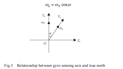
As long as the output of the gyroscope in the corresponding position is measured, the Angle between the sensitive axis of the gyroscope and the true north direction can be calculated by equations (1) and (3) :

In summary, theoretically, the north finding result can be obtained from the output of the gyroscope at a single position, but the result of unit setting is directly related to the zero bias, zero bias stability, scale factor, random noise and other parameters of the gyroscope itself, and these parameters cannot be determined. Therefore, the precision of the north finding method using unit setting is very low.
2.2 Tracking System
The tracking system mainly includes three-axis MEMS gyroscope and three-axis MEMS accelerometer, data acquisition and professional navigation software, which can provide the position, speed and attitude information of the moving carrier. Two kinds of inertial sensors are installed according to the three positive directions of the carrier coordinate system. The three-axis MEMS gyro is used to measure the angular velocity components of the three axes of the carrier motion relative to the inertial coordinate system. Three-axis acceleration component. The system mainly uses the strapdown attitude matrix to complete the linear acceleration component. The strapdown attitude matrix is used to complete the coordinate transformation, and the linear acceleration along the three axes of the carrier coordinate system is transformed into the linear acceleration along the three axes of the navigation coordinate system, and the velocity and position parameters of the carrier are obtained by solving. The angular velocity component along the three axes of the carrier coordinate system is converted into the angular velocity component along the three axes of the navigation coordinate system, and the attitude parameters of the carrier are obtained by solving.
3.North finding system algorithm design
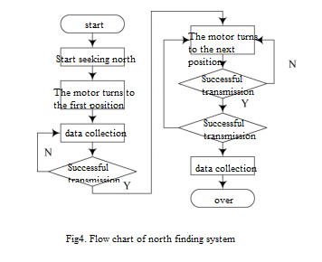
Based on the different acquisition locations, it can be divided into multi-position scheme, continuous rotation scheme, two-position scheme, four-position scheme and so on. Although the form of the scheme is different, the basic principle is similar, and each has its own characteristics. The algorithm based on static four-position north finding system is simple and easy to solve in water. Horizontal position does not need latitude information and other outstanding advantages, this paper adopts a four-position scheme for measurement, the software flow chart is as follows:
4 Conclusions
In this paper, a new direction alignment instrument with MEMS gyro as the core sensor is designed, which reduces the cost of the original fiber optic gyro sensor. If you are interested in the direction alignment instrument of MEMS technology, you can understand the specific parameters of ER-MNS-05 and ER-MNS-06.
More Technical Questions
1.Research on downhole north seeker
2.Research on orthogonal monitoring technology of north finder
3.Modeling and filtering in signals collected by FOG north seekers
4.Error Modeling and Compensation Analysis of North Finder Based on FFT
5.Research and use of north finder for mining drilling rigs
6.System Analysis of MEMS North Seeker
Products in Article
