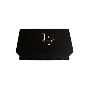
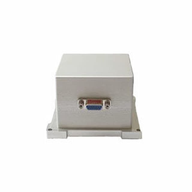
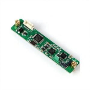
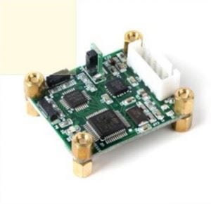
North finder can provide accurate heading information for the carrier, and plays an important role in many fields such as national defense, military, civil and so on. Strapdown north finder mainly uses optical gyroscope as its key component, the basic principle is to make the gyroscope sensitive axis measure the horizontal component of the earth angular rate (ground speed) in different directions, and independently determine the course Angle of the attached carrier relative to the geographical true north, without interference and influence from the external magnetic field or other environment. It can also be combined with the accelerometer for horizontal attitude measurement and compensation.
The accuracy of the north finder is mainly limited by the drift noise of the inertial element, which mainly includes constant drift and random drift. How to suppress the measurement error becomes the focus of the research of the north finder. The traditional scheme is to adjust the north finder on the horizontal plane, adopt the static multi-position measurement method, and use the symmetrical position to offset the influence of the inertial element constant drift on the system accuracy, so as to determine the heading Angle of the carrier, but the north finding accuracy of this method is easily limited by the measurement number and sampling time. Starting with the output models of gyroscope and accelerometer under the rotating condition of static base, this paper designs a fast north finding scheme based on orthogonal detection technology, which can effectively suppress the constant drift and random drift of inertial elements, improve the north finding accuracy in a short time, and output horizontal attitude information with a certain precision. And the whole process of north finding does not need to rotate the platform to adjust on the horizontal plane, which is convenient for practical engineering applications.
1.Orthogonal detection technology and north finding algorithm
Orthogonal detection technology was first used to extract weak signals under strong noise background and suppress constant drift and 1/f noise (such as the drift noise caused by the influence of temperature on circuit components). It has been widely used in resource exploration and precision measurement, especially for sinusoidal signal and square wave signal. The principle is that according to the characteristics of the input signal, two unit orthogonal reference signals rI (t) and rQ (t) with the same frequency as the input signal and the phase difference of 90° are generated, and the input signal x(t) containing noise is multiplied and summed respectively, and then filtered through the low-pass filter to remove the noise term; The output (I and Q components) of the orthogonal detector are sensitive to the amplitude and phase of the input signal x(t), achieving the purpose of both amplitude and phase detection, and completing the extraction of the characteristic parameters of the input signal. The principle block diagram is shown in Figure 1.
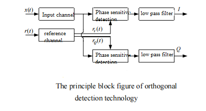
Under the condition of no noise, the single-frequency input signal and the two reference signals are unit quadrantal square wave signals. After the data is sampled as an integer multiple of the rotation period, the simultaneous component (I) and vertical component (Q) of the output of the orthogonal detector are as follows:


Then, the amplitude and phase in input channel signal x(t) are calculated according to formula (1), as shown below:

According to the above principle, through the output of acceleration f p, A and B can be obtained, due to the horizontal attitude angle [-90°,90°], in this interval the sine inverse trigonometric function is monotonic, so the two horizontal attitude angles can be solved singly:

Since the horizontal attitude angles have been obtained, M and N can be obtained by using the orthogonal detector through the output of the accelerometer. Then the sine and cosine expressions of heading angle y and the principal value of heading angle can be calculated

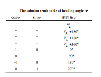
As the heading Angle [0°, 360°], combining the expression cosy and the sign of siny, the heading angle can be determined, and the whole north-seeking solution process can be completed. The truth value of course angle y is shown in Table 1.
2.North finder system composition
The north finder system should be combined with practical engineering applications, and the rotation axis should be installed on a vertical base, which can effectively avoid the reciprocating tumbling of the accelerometer in a g gravity field, and ensure that the accelerometer works in the linear measurement area as far as possible to reduce the measurement error. The rotating platform is parallel to the carrier plane (base) and can be rotated around the rotating axis. The sensitive axes of the gyroscope and accelerometer on the rotating platform are parallel in the same direction and perpendicular to the rotating axis, and the installation error can reach the order of arcseconds. Since there is only one angle difference between p and b, the heading angle of the carrier can be calculated by combining the heading angle of the inertial element with the reading angle output of the angle encoder.
Because the rotation mode is one-way constant speed rotation, a conductive ring must be used to connect the signal and power cables. Servo system drive mode adopts PWM control mode, in order to make the speed accuracy reach a certain index, the rotation control system is designed into a three-ring structure: current ring, speed ring and position ring, the Angle measuring unit adopts relative angle encoder, and the rotating platform has the function of automatically turning to angle zero.
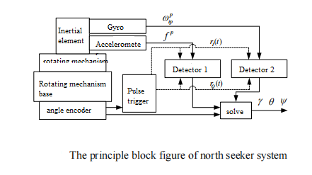
The reference signal selects two quadrature square wave signals with a phase difference of 90°. When the rotating platform turns to the integer multiple of 90° output of the Angle sensor, the software interrupts to reverse the polarity of the reference square wave signal respectively. Firstly, at the angle zero position of the rotating platform, the quadrantal of the horizontal attitude angle and the linear combination term of the heading Angle and the ground velocity component are determined by the positive and negative signs of the output data of the accelerometer and gyroscope. The output data of 120s inertial element is collected when the speed reaches a steady state, avoiding the sudden speed change of the motor. After the collection is completed, the motor stops rotating. Firstly, according to the output of the accelerometer, the orthogonal detector is used to calculate two horizontal attitude angles. Then according to the output of the gyro, the orthogonal detector is used to calculate the heading angle. The principle block diagram of the north finder system is shown in the figure.
3.Conclusion
Based on the analysis of the output characteristics of the inertial element under the condition of static base, a fast north finding scheme based on the orthogonal detection technology is proposed. The north seeker can not only calculate the heading angle, but also give the horizontal attitude angle with certain precision, eliminating the adjustment of the level of the rotating platform in the process of north finding. The north seeking accuracy is not affected by the constant drift of inertial devices, and can effectively suppress random drift error, improve the north seeking accuracy, and meet the needs of some projects. If you need, you can click to view the specific product parameters ER-FNS-03,ER-MNS-05,ER-MNS-06, or talk to us in detail.
More Technical Questions
1.Error Modeling and Compensation Analysis of North Finder Based on FFT
2.Modeling and filtering in signals collected by FOG north seekers
3.Research and use of north finder for mining drilling rigs
4.System Analysis of MEMS North Seeker
5.How to Process the Data of FOG North Seeker
6.Research on Anti-environmental Interference of North Finder
Products in Article
