MEMS gyroscope is a kind of MEMS inertial sensor which uses Coriolis effect to detect the rotational angular rate of objects. It can integrate the sensitive structure and peripheral measurement and control circuit on the same silicon chip, and has the advantages of low cost, small size, light weight and low power consumption. The sensitive structure is the core component of MEMS gyro sensor, which is directly related to the performance of the gyroscope such as scale factor, zero bias and anti-vibration. This paper will introduce the basic knowledge of MEMS gyros in detail from the sensitive structure, detection circuit and integrated package of MEMS gyroscope.
Sensitive structure of MEMS gyro
As shown in Figure 1, the X-axis is the driving axis of the MEMS gyroscope, the Y-axis is the detection axis, and the Z-axis is the angular rate input axis. The mass block is connected to the anchor point through the detection beam, the drive beam, the top beam and the support beam, and the movable structure is suspended on the base through the anchor point. After the drive voltage is applied to the drive comb teeth, the two mass blocks vibrate along the X axis, when there is an angular rate input in the Z axis, the two mass blocks vibrate along the Y axis under the action of Coriolis force, forming a differential detection capacitance. The change of the detected capacitance is proportional to the input angular rate, and the input angular rate can be measured by measuring the change of the capacitance. When the MEMS gyro is subjected to vibration, shock and other linear acceleration, the direction of inertia force received by the two mass blocks is the same, so that the common mode signal output is formed in the detection direction. The differential detection can suppress the common mode error and reduce the influence of vibration and shock on the gyro output.
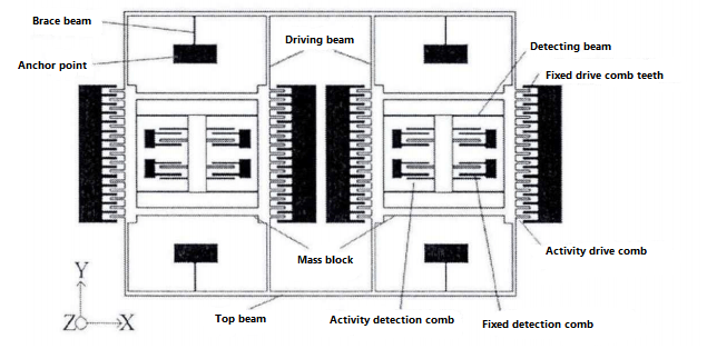
Figure 1 Schematic diagram of MEMS gyro sensitive structure with dual mass line vibration
MEMS gyro detection circuit
The MEMS gyroscope ASIC circuit drives the closed loop and detects the open loop mode. The circuit block diagram is shown in Figure 2. The driving loop includes a C-V conversion unit, a ∑-∆ A/D conversion unit, a PLL automatic gain control unit and a ∑-∆ A/D conversion unit. Because of the digital closed loop mode of ∑-∆, the influence of parasitic mode on the device performance can be effectively suppressed, the anti-interference ability of the gyroscope is improved, and the electrostatic adsorption phenomenon is avoided.
The detection loop is in the form of open loop, including C-V conversion unit, ∑-∆ mod-digital conversion unit, compensation unit and filter unit, and finally realizes the output of angular rate signal, temperature signal and self-detection signal through SPI interface. Through digital compensation and filtering, the precision and environmental index of gyro can be improved effectively.
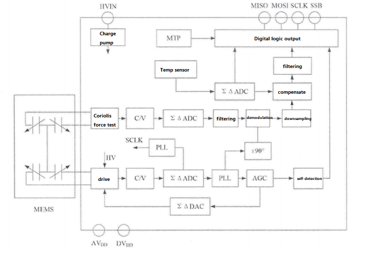
Figure 2. MEMS gyro ASIC circuit block diagram
Integrated package of MEMS gyro
In order to reduce the volume and weight of MEMS gyro and improve the reliability, a two-piece integrated package is used to encapsulate the sensitive structure and ASIC circuit in a ceramic package. Compared with the MEMS gyro integrated with discrete devices, the two-chip integrated sensitive structure and ASIC chip realize signal interconnection through lead bonding, which has short lead length and small parasitic capacitance. On the other hand, the two-piece integrated package can effectively reduce the volume and weight of the device, improve the reliability of the device, and achieve a breakthrough in the volume, weight and cost of MEMS gyro. The gyro integrated package scheme is shown in Figure 3. The ceramic package shell is LCC30 package, and the sensitive structure chip and ASIC circuit are integrated inside the wafer-level vacuum package.
The integrated MEMS gyroscope weighs only 1.85 grams, consumes only 0.125W, and has angular rate signal output, temperature signal output and self-detection state output, which can meet the needs of most engineering applications.
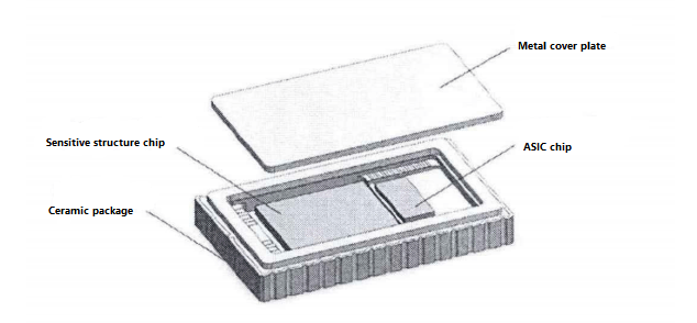
Figure 3 MEMS gyro integrated package schematic diagram
ER-MG-057 and ER-MG2-50/100
MEMS gyro is mainly divided into navigation level, tactical level and consumer level according to the accuracy level. Consumer-grade MEMS gyroscopes are mainly used in smart phones, VR, etc., while navigational and tactical levels are mainly used in oil logging, aerospace, mapping, drones and other fields.
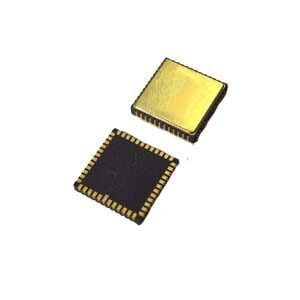
The ER-MG-057 is a tactical MEMS gyroscope in an LCC package with a scale factor of 20000LSB/°/s and zero bias instability of 1dph. Its dimensions are 11×11×2mm and its power consumption is only 0.2W.
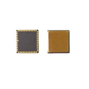
The ER-MG2-50/100 is a navigation-grade MEMS gyroscope, also using LCC package, the scale factor is 160,000-80,000 LSB/deg/s under the condition of 25℃, zero bias instability is 0.01-0.02deg/hr, the accuracy of the navigation level is higher than that of the tactical level, more suitable for the field of high precision. Similarly, its dimensions are 11×11×2mm and its power consumption is only 0.2W. Figure 4 is a physical picture of a MEMS gyroscope.
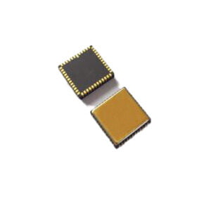
Figure 4 MEMS gyro diagram
Conclusion
This paper introduces the sensitive structure, detection circuit and integrated package of MEMS gyro, and introduces the precision level of MEMS gyro of different levels by taking two MEMS gyro of different levels as examples.
If you are interested in MEMS gyro knowledge, please contact us.
More Technical Questions
1.Integrated method of three-axis MEMS gyroscope
2.Development history of MEMS gyroscope
3.MEMS gyroscope processing technology
4.Evolution of resonant structure of high precision MEMS gyroscope
5.Stochastic error modeling method of MEMS gyroscope
6.Signal Denoising Principle And Evaluation Index of MEMS Gyroscope
Products in Article
High precison MEMS Gyroscope
High Accuracy Single-Axis MEMS Gyro
High Precision Stable-Control MEMS IMU

