

In recent years, with the rapid development of petroleum logging, aerospace, mining, surveying and mapping and other fields, the precision and long-term stability of precision instruments such as MEMS gyroscope has become more and more urgent. Studies have shown that the dimensional instability of materials is one of the main reasons for the poor accuracy and stability of inertial instruments. Dimensional stability is different from thermal expansion or thermal cycling performance, it is the main performance index of precision mechanical parts materials, refers to the ability of parts to maintain their original size and shape in a specific environment.
MEMS gyroscope based inertial instrument material
There are four main types of inertial instrument component materials, one is metal (such as aluminum and aluminum alloy, stainless steel, copper and copper alloy, titanium alloy, beryllium, gold, etc.) and its composite materials; Second, functional materials (such as iron-nickel soft magnetic alloy, samarium-cobalt hard magnetic alloy, Al-nickel-cobalt hard magnetic alloy, etc.); Third, organic polymers (such as polytetrafluoroethylene, rubber, epoxy resin, etc.); The fourth is inorganic non-metal (such as quartz glass, processable ceramics, etc.), of which the largest amount is metal and its composite materials.
In recent years, we have made breakthroughs in high-precision machining manufacturing, low/stress-free assembly technology, but we still find that after the delivery of the instrument, there is a slow drift in accuracy and cannot achieve long-term stability. In fact, after the structural design, parts processing and assembly process is determined, the long-term stability of the instrument accuracy depends on the intrinsic characteristics of the material.
The intrinsic properties of the material (such as microscopic defects, second phase, grain size, texture, etc.) directly affect the dimensional stability of the material. In addition, the instrument material will also undergo irreversible dimensional changes under the interaction with the external environment (stress field, temperature field and time, etc.). Figure 1 shows the relationship between the accuracy of the inertial instrument and the service conditions, material microstructure and size change. Taking MEMS gyroscope as an example, its working conditions and storage environment have an impact on the dimensional stability of the material. Even if the MEMS gyroscope has a temperature control system, if the microstructure of the material itself is unstable, there is a metastable second phase, or there is macro/micro residual stress during assembly, the accuracy of the instrument will drift.
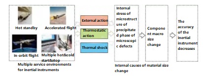
Figure 1 The relationship among the accuracy of inertial instruments, service conditions, microstructure and dimensional changes
Influencing factors of material change
The intrinsic properties of MEMS gyroscope materials mainly include microscopic defects, second phase, grain, texture and internal stress, etc. The external environmental factors mainly interact with the intrinsic properties to cause dimensional changes.
1. Density and morphology of microscopic defects
Microscopic defects in metals and alloys include vacancies, dislocations, twins and grain boundaries, etc. Dislocation is the most typical form of microscopic defect, which refers to the defects formed by irregular arrangement of atoms in regularly arranged crystals, such as the absence or increase of half atomic plane of edge dislocation. Due to the dislocation introducing free volume into perfect crystals, the material size changes are caused, as shown in Figure 2. However, in the case of the same number of atoms, the existence of dislocation makes the free volume around the atoms appear, which is reflected in the increase of the alloy size.
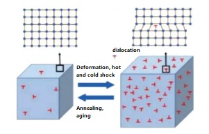
Figure 2 Schematic of the effect of the microscopic defects density in materials on the dimension of the material
2. Influence of grain and texture on stability
The relationship between the strain ε of the metal or alloy under applied stress σ and the grain size d of the material, the density ρ of the movable dislocation, the stress σ0 required for the first dislocation to start, and the shear modulus G of the material is derived:
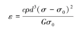
It can be seen from the formula that grain refinement can reduce the strain generated, which is also the guiding direction of microstructure regulation in the stabilization process.
In addition, in actual production, when using extruded bars and rolled plates to process precision instrument components, it is also necessary to pay attention to the anisotropy of the material, as shown in Figure 3. Taking 2024Al alloy for mechanical gyro frame as an example, the frame in figure 3(a) generally adopts extruded 2024 aluminum alloy bar. Due to large plastic deformation, the grains will show preferential orientation to form texture, as shown in figure 3(b) and (c), texture refers to the state in which the crystal orientation of the polycrystalline material deviates significantly from random distribution.
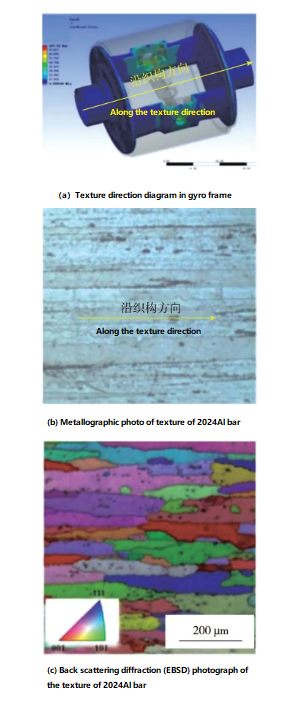
Figure 3 Microstructure of 2024Al alloy rod for mechanical gyroscope frames
3. The influence of environment on the dimensional stability of materials
In general, inertial instruments need to maintain long-term accuracy stability under conditions such as large overload, vibration and shock, and temperature cycling, which puts forward more demanding stabilization requirements for the microstructure and properties of materials. Taking instrument-grade SiC/2024Al composites as an example, long-term dimensional stability is achieved with stabilization process in the manufacturing of inertial instrument structures. The results show that the size change amplitude (~ 1.5×10⁻⁴) caused by the constant temperature holding process of SiC/ pure aluminum composite (only the internal stress plays an effect on the size change) is greater than that of the aluminum alloy constant temperature holding process (only the aging precipitation plays an effect on the size change) (~ -0.8×10⁻⁴). When the matrix becomes Al alloy, the effect of the internal stress of the composite on the dimensional change will be further amplified, as shown in Figure 4. In addition, under different service environments, the internal stress change trend of the same material is different, and even the opposite size change trend will be shown. For example,SiC/2024Al composites produce compressive stress release at a constant temperature of 190 ° C, and the size increases, while tensile stress release occurs at 500 cold and hot shocks at -196 ~ 190 ° C, and the size decreases.
Therefore, when designing and using aluminum matrix composites, it is necessary to fully verify their service temperature load, initial stress state and the type of matrix material. At present, the process design idea based on stress stabilization is to carry out cold and thermal shock covering its service temperature range, release internal stress, form a large number of stable dislocation structures inside the composite material, and promote a large number of secondary precipitation.
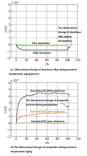
Figure 4 Dimensional changes in aluminium alloys and composites during constant temperature aging
Measures to improve dimensional stability of components
1. Regulation and optimization of micro-defects
Selecting new material system is an effective way to control micro-defects. For example, the use of instrument-grade SiC/Al composites,SiC ceramic particles to pin the dislocation in the aluminum matrix, reduce the density of movable dislocation, or change the type of defect in the metal. Taking SiC/Al composites as an example, the research shows that when the average distance between ceramic particles in the composites is reduced to 250 nm, the composite with layer fault can be prepared, and the elastic limit of the composite with layer fault is 50% higher than that of the composite without layer fault, as shown in Figure 5.
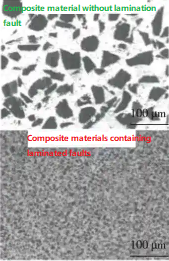
Figure 5 Two kinds of composite material morphology
It should be pointed out that when developing the process route of organizational control, it is also necessary to select the appropriate material system and cold and thermal shock process parameters in combination with the stress conditions and working temperature range of the inertial instrument service environment. In the past, the selection of material system and process parameters relied on experience and a large number of performance data, which resulted in insufficient theoretical basis for process design due to the lack of micro-structure support. In recent years, with the continuous development of analytical testing technology, quantitative or semi-quantitative evaluation of microscopic defect density and morphology can be achieved by means of X-ray diffractometer, scanning electron microscope and transmission electron microscope, which provides technical support for material system optimization and process screening.
2. Regulation of grain and texture
The effect of texture on dimensional stability is the anisotropy that causes the dimensional change. As mentioned earlier, the MEMS gyroscope frame has extremely strict vertical requirements in the axial and radial direction, and the processing error is required to be controlled in the order of microns to avoid causing the centroid deviation of the MEMS gyroscope. For this reason, the 2024Al extruded bar was subjected to deformation heat treatment. Figure 6 shows the metallographic photos of 40% axial compression deformation of the extruded 2024 aluminum alloy and the microstructure photos before and after thermal deformation. Before the deformation heat treatment, it is difficult to calculate the size of the axial grain, but after the deformation heat treatment, the equiaxial degree of the grain at the edge of the bar is 0.98, and the equiaxial degree of the grain is significantly increased. In addition, it can be seen from the figure that the small deformation resistance difference between the axial and radial of the original sample is 111.63MPa, showing strong anisotropy. After deformation heat treatment, the axial and radial small deformation resistance values were 163 MPa and 149 MPa, respectively. Compared with the original sample, the ratio of axial and radial small deformation resistance changed from 2.3 before deformation heat treatment to 1.1, indicating that the anisotropy of the material was better eliminated after deformation heat treatment.
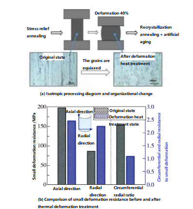
Figure 6 Schematic diagram of isotropic treatment, microstructure changes, and performance testing of aluminum alloy rod
Therefore, when aluminum alloy bars or plates must be used to process inertial instrument components, it is recommended to increase the deformation heat treatment link, eliminate the texture, obtain isotropic organization, and avoid the anisotropy of deformation. The statistical information of texture can be obtained by EBSD in SEM, TKD in TEM or three-dimensional XRD, and the texture changes can be quantitatively analyzed.
Conclusion
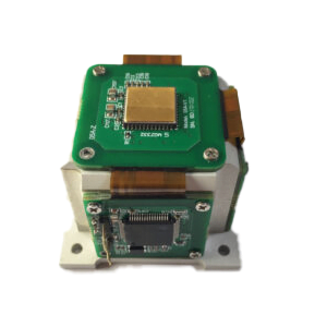
Based on the urgent need of long-term accuracy stability of inertial instruments, this paper systematically reviews the influence of dimensional stability from the perspective of material science, and puts forward how to improve the long-term accuracy stability of inertial instruments from the intrinsic characteristics of materials. The ER-MG2-200, in an LCC ceramic package, is an upgraded north-finding MEMS gyroscope based on the ER-MG2-50/100, and its range has been increased from 50-100°/s to 200°/s, achieving a milestone. Materials are critical to the long-term stability of , and it is the basis for their best performance.
I hope that through this article you can understand the knowledge of MEMS gyro, want to know more information can read related products and articles.
More Technical Questions
1.Integrated method of three-axis MEMS gyroscope
2.Development history of MEMS gyroscope
3.MEMS gyroscope processing technology
4.Evolution of resonant structure of high precision MEMS gyroscope
5.MEMS Gyroscope: Sensitive Structure | Detection Circuit | Integrated Package
6.Comparison Of Technical Specifications Of Navigation Grade MEMS Gyroscope
Products in Article
 3-Axis North-Seeking MEMS Gyro
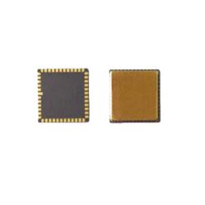
 High Precision Navigation MEMS Gyroscope
 2-Axis North-Seeking MEMS Gyro
 High Performance Navigation Grade MEMS Gyroscope