1. Interferometric fiber optic gyro
The linear relationship between the spin rate and the output of the fiber optic gyroscope can effectively solve the sensitivity and dynamic range of the fiber optic gyroscope. According to the linearization characteristics of interferometric fiber optic gyroscopes, fiber optic gyroscopes can be divided into open-loop fiber optic gyroscopes and closed-loop fiber optic gyroscopes.
1.1 Open-loop fiber optic gyroscope
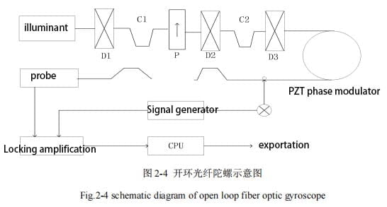
Open-ring fiber gyro is composed of laser, polarizer, light detector, fiber coil, fiber coupler and piezoelectric ceramics, phase modulator structure. Among them, A1, A2, A3 depolarizer, U is the polarizer, D1, D2 is the single mode coupler, first of all, the fiber optic gyroscope phase modulates the input signal, and then the modulated signal is amplified through the amplifier, and then demodulated through the demodulator, and then the demodulated signal is transmitted to the main control chip through the RS422 bus. The master chip sends the accepted data to the host computer through the RS232 bus, and the host computer calculates the attitude Angle of the carrier through the north finding algorithm, and finally displays the attitude of the current object to the user in the form of a visual interface. Figure 2-4 shows the open-loop fiber optic gyroscope.
On the optical fiber coil, the vector quantity after the stacking of the light waves in the direction of the direction of the clockwise needle and the reverse needle is
![]()
When the polarization of the light vector in both directions on the fiber coil is the same, then the light intensity after the interference of the two beams is

In the formula: I 0= | E0 | 2, it can be obtained from the formula that the light intensity of the interferometric fiber optic gyroscope changes with the Sagnac phase shift as shown in the figure as shown in 2-5.
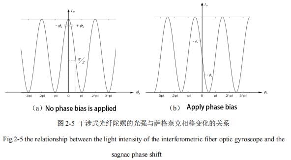
From the curve in the figure, we can see:
(1) The output light intensity of the interferometer changes periodically with the Sagnac phase shift. The rotation angular rate of the system requires the phase shift s of the interferometric fiber optic gyroscope to be within the first interference fringe. The rotation angular rate of the system can be obtained from the output formula of the interference light intensity as follows:

(2) Because the output light intensity of the fiber optic gyro and the Sagnac phase shift is a cosine function change, it cannot be passed Sagnac phase shift symbol to determine the direction of rotation.
(3) When no bias is applied to the system, the light intensity of the fiber optic gyro output is zero at odd times of pai; right
When the bias is applied, the light intensity of the fiber optic gyro output is zero at an odd multiple of pai/2.
1.2 Closed-loop fiber optic Gyroscope
On the basis of open-loop fiber optic gyroscope, closed-loop fiber optic gyroscope further enhances the interference of two beams of incident fiber coil, so that the interference phase difference between the two beams of light always maintains a constant no matter how fast the fiber optic gyroscope rotates. The methods adopted are: A feedback control device is added to one end of the circular fiber coil to introduce a feedback phase shift between the two beams of light in the fiber coil in response to the rotation Angle rate of the system, because the amplitude of the feedback phase shift generated by the two beams of light in the system is the same as the amplitude of the phase shift generated by the Sagnac effect, and the direction of the two moves is opposite. This can offset the phase difference caused by the rotation of the system. The closed-loop fiber coil is generally composed of a coupler, a polarizer, a PZT phase modulator and a feedback element.
In a closed-loop control system, as shown in Figure 2-6 (a), the square wave signal Vm (t) input by the system is paired at different times
The same phase modulation is applied to the two beams, as shown in Figure 2-6 (b, c).
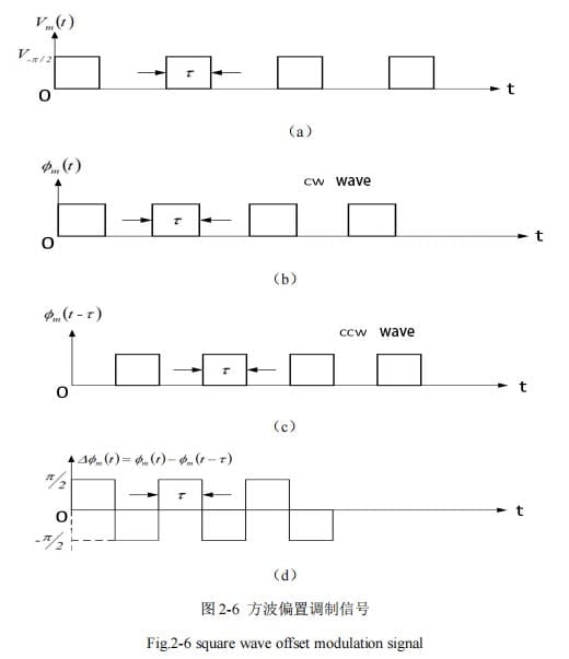
As can be seen from the figure above, the phase shift of light waves on the fiber coil changes between two adjacent half-cycles of square-wave signal modulation. When the fiber gyro rotates, the bias point will move, and the system will output a square wave signal with the same frequency as the modulated signal, so that the output voltage is:
In this design concept, the offset phase modulation waveform is always centered at zero, and when the modulation waveform is loaded onto the optical wave of the optical fiber coil, the phase shift of the optical wave on the optical fiber coil is always changing on the same half period as the square wave modulation signal, and the system does not produce any phase shift when the system stops rotating.
2.Summary
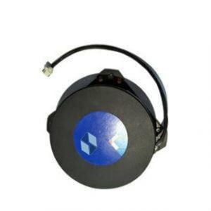
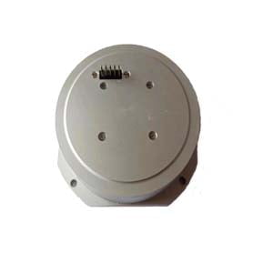
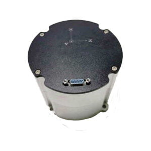
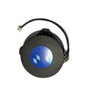
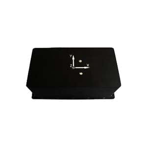
According to the physical structure of the fiber optic gyroscope itself, the optical device and the noise generated by the light detector have a great influence on the accuracy and sensitivity of its output. And the fiber optic gyro itself is particularly sensitive to the interference of the external environment, as long as the outside world has a small jitter, the output of the fiber optic gyro will change, resulting in the error between the fiber optic gyro output data and the real data. Because there are many factors outside the fiber optic gyroscope will cause random drift, that is, random error. In order to eliminate these random errors, it is necessary to establish reasonable models for the values and distribution of these random drifters, and according to these models, we can further understand the working principle of the fiber optic gyroscope, and then optimize the model according to the results of model testing, so as to further improve the performance of the gyroscope. Ericco's fiber optic gyro ER-FOG-50, ER-FOG-60, ER-FOG-70 has the characteristics of small size, pure solid state, long life, etc. If you are interested in obtaining more technical data, you can contact me at any time.
More Technical Questions
1.Temperature Drift and Compensation Method of FOG Gyro
2.Analysis of Fiber Optic Gyroscope Output Signal
3.Research on miniaturization technology of fiber optic gyroscope
4.Application of fiber optic gyroscope in aviation field
5.Analysis of Temperature Drift Compensation Method for Fiber Optic Gyroscope
6.Processing and Analysis of Random Drift Error Based on Fiber Optic Gyroscope
Products in Article
