1.Application Products
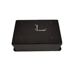
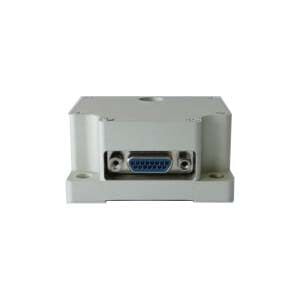
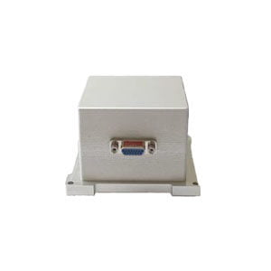
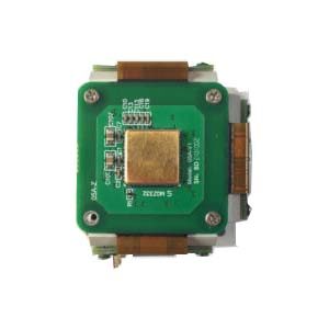
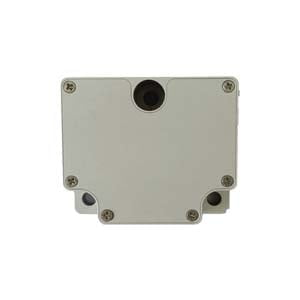
ER-FNS-03 Low Cost 3 Axis FOG North Seeker
2.Acquisition Software Description
The simplified version of the ER-FNS-03 series North finder acquisition software is shown below:
Navigation data module: After the system's north seeking is completed, the alignment information is displayed on the left side of the area, and the right part of the system tracks the three-dimensional attitude information of the system in real time.
Control command module: “North find command” can re-do the north search under the condition of continuous power; the latitude, longitude and altitude of the current work place can be entered in the three edit boxes of latitude, longitude and location (just for mobile phone positioning). You can bind the latitude and longitude information and write it into the internal memory of the system immediately. After sending, click the "North Search Command" to search for the north at the newly entered latitude and longitude, without losing power.
Sensor data module: includes the raw output data of the gyroscope and accelerometer; the internal counter counts when it is powered on, and is cleared after clicking the "North Finding Command"; the latitude, longitude, and height are the binding information.
The data is stored in the current directory of the software, named "0924205117imu_data.txt" (document creation time), and the data columns are triaxial gyroscope, triaxial plus table, triaxial attitude angle, latitude, longitude, and height.
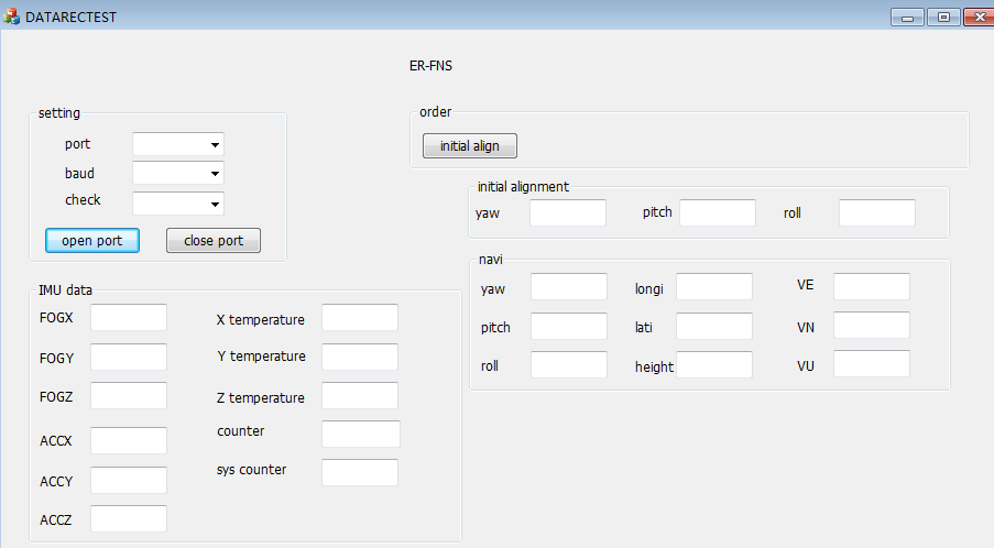
Figure 5 ER-FNS-03 series North finder acquisition software interface
3.Test procedure description
The ER-FNS-03 series north seeking instrument should be tested according to the correct operation order. The test steps are briefly explained as followed:
(1) System installation: ER-FNS-03 series north finder is fixed on the reference surface of the test bench through the bottom surface;
(2) Connector connection: connect the power supply and data interface as required, see section 3 for details;
(3) Power on the system: After the external linear power supply is determined to be debugged, check that there is no problem in the connection of each part, turn on the external linear power supply, and check whether the power supply current is within the normal power consumption range. In small cases, power-off inspection is required, and the test can be continued when the current is correct;
(4) System work: After the system is powered on, the data interface connected to the SX1 should have data output. For details, see Part 3. Use the provided ER-FNS-03 series north seeking instrument acquisition software to collect data and power on the system. After that, it takes 5 minutes to align the time (north seek time). Try to keep the system in a static state within 5 minutes. After the alignment is completed (after 5 minutes), it will enter the navigation phase. At this time, turn the bearing device and the north seeker will be real-time. Follow the changes of the three attitude angles. If you need to re-align (north seek), press the third part and click the "north seek command" button to re-north seek (third part).
More Technical Questions
1.What is the Device Interface Definition of MEMS North Seeker
2.How to Use Acquisition Software of MEMS North Seeker
3.What is the Device Interface Definition of FOG North Seeker
4.What Performance is the FOG sensor in FOG North Finder
5.What is the System Structure of FOG North Finder
6.What Performance is the Accelerometer Sensor in FOG North Finder
Products in Article
