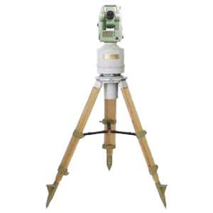
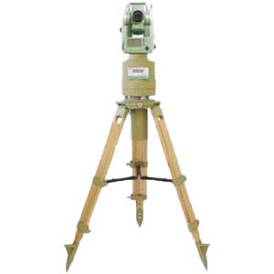
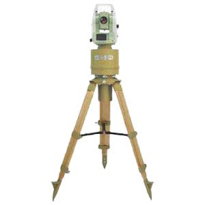
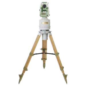
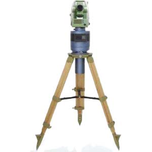
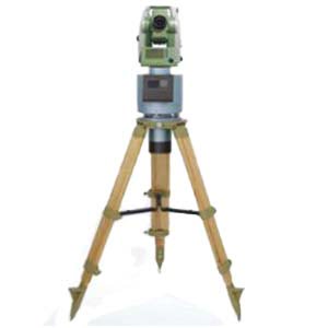
The gyro theodolite is a high-precision precision directional instrument that integrates light, machinery and electricity. It is widely used in various departments such as mining, construction, surveying and mapping, and military. Because it is not limited by time and environment, the observation is simple, convenient, and efficient, and it can ensure high accuracy. Therefore, it is an advanced directional instrument. Compared with traditional geometric orientation, gyro orientation has huge advantages. . However, due to design limitations and improper usage of domestic gyro power supplies, the repair rate of domestic gyro-theodolite purchased by most production units and many universities and research institutes has increased sharply. In view of the huge cost of going to the manufacturer for repairs and the fact that ordinary electrical repair personnel do not understand the principle of gyro orientation, the author has summarized the following gyro-theodolite maintenance procedures through repeated practice for reference by relevant units.
1.Common fault phenomena and maintenance logic
Fault phenomenon 1: The main switch K1 of the gyro power supply is placed in the lighting position and the starting position. The lighting light does not light up and the gyro motor cannot start (see Figure 1 for the gyro theodolite panel). See Figure 2 for maintenance logic.
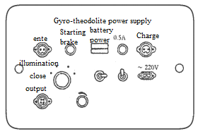
Figure 1 Power box panel
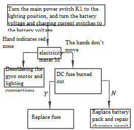
Figure 2 Maintenance logic one
Fault phenomenon 2: Turn the main switch (K1) to the lighting position, the observation window light is on, but the gyro motor cannot start. See Figure 3 for maintenance logic.
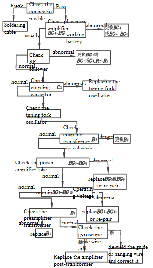
Figure 3 Maintenance logic two
Fault phenomenon three: When the main switch is turned to the start position, the gyroscope can start, but the rotation speed is low and cannot be oriented. See Figure 4 for maintenance logic.

Figure 4 Maintenance logic three
More than 90% of faults can be eliminated by following the above maintenance procedures. Although changes in the parameters of individual non-vulnerable components in the circuit can cause abnormalities in the instrument, the instrument can generally still work, and this phenomenon has not happened so far. As for the optical longitude and latitude of the instrument, when estimating the measurement method, all errors are considered to be equal and are all m, then
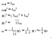
If the side length is set out, the relative error allowed is 1/T

2. Alignment error analysis
The analysis of alignment errors in "Engineering Surveying" is an analysis of an intermediate ruler section in a multi-foot section. The first and last sections each have only one alignment point, and there is alignment error only at one end, that is, there is no alignment error at points A and B (see Figure 2).

Summarize
Steel rulers are widely used to measure edges. In order to improve the accuracy of setting out and point accuracy, the prediction of measurement methods must be carefully carried out. In particular, accidental errors and systematic errors should be strictly distinguished when classifying. Otherwise, the prediction will be allowed. The error increases, and the requirements for engineering stakeout are relaxed, causing the point accuracy of the stakeout to fail to meet the requirements. Therefore, error prediction and measurement method prediction are the basis for meeting the point position accuracy stakeout. Only under this condition can the stakeout point position meet the accuracy requirements. ERICCO's gyro-theodolite is carefully preserved. If it encounters a malfunction, it will be repaired and operated according to strict requirements, such as ER-GT-02:
ER-GT-02 (≤3.6") Features:
- Orienteering accuracy ≤3.6" (1σ);
- Pit interference ability is strong, integrated fuselage design, compact structure, stable performance;
- Has the functions of low lock, automatic zero observation and etc.
If you want to learn about or purchase our gyro-theodolite, please contact our relevant technical staff.
More Technical Questions
1.Application of gyro-theodolite orientation in shaft contact measurement
2.Accurate Alignment Method for Gyro Theodolite Calibration System
3.Application of Gyro-Theodolite Orientation in Mine Surveying
4.Effect of latitude on gyroscopic theodolite
5.What is the Structure of a Gyro Theodolite?
6.How To Orient The Gyro Theodolite?
Products in Article
