1. Principle of fiber optic gyro instrument inspection vehicle
1.1 Working principle of fiber optic gyro
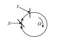
It is assumed that two beams of light with the same characteristics are formed from the same light source in a closed optical path and propagate in opposite directions, and the angular speed of the optical fiber coil rotation in space is calculated by the optical path difference generated by the two beams at the convergence point, that is, the Sagnac effect.
The following diagram shows the Sagnac effect. X is the incident point of the beam, Y is the exit point of the beam, and Ω is the angular rate.
1.2 Principle of chord measurement
The detection technology of track irregularity based on fiber optic gyro (FOG) is an advanced track detection method in the current string measurement method. Using the gyroscope to measure the Angle, the transfer equation between the track direction is changed by the Angle of the track detector, and the track direction irregularity data is obtained.
2. Analysis of measurement results
2.1 Test scheme
The school has a good surrounding environment, stable geological conditions and good visibility conditions, which provides a favorable external environment for the implementation of the program. The converted length of the track is about 1040m. Among them, about 110m of ballastless track can be used for the detection of the track inspection system.
Fiber optic gyro is the main sensor for measuring track irregularity with track inspection car, and its working characteristics are related to the accuracy of track inspection equipment. The test content of track smoothness mainly includes gauge, high height, high height, level, track direction and so on.
We mainly introduce the gauge, level and track direction.
The distance between the 16 mm position under the inner side rail surface of the two rail heads is called the gauge. The difference between the top height of the two rails is called the level. Through repeated measurement of the track level, gauge and track direction of the detection field, the relative internal and external coincidence measurement accuracy of the track detector based on fiber optic gyro is verified. The stability of the measuring system, that is, the difference of the measurement results when the track detector repeatedly measures the geometric state parameters of the same section of track. External coincidence accuracy indicates the accuracy of the track inspection equipment, that is, the difference between the measured results and the reference value of the track geometric state parameters should be small enough. The measurement accuracy of internal coincidence is relative difference, and the measurement accuracy of external coincidence is absolute difference.
We use the level 0 digital display track ruler to measure the gauge and level at each mark of the track in the detection field for three times, and the average value is taken as the reference value of the gauge and level, and the average value of the track direction of the 3 times manual pulling string is taken as the reference value of the track direction. After the measurement is completed, the measured data are numbered according to the mark number, and then the measurement difference of gauge, water level, rail forward and forward push at each mark of the detection field track, the repeated measurement difference and the difference between each measurement value and the reference value are calculated, and the measurement accuracy is calculated.
2.2 Test results
The track detector distributed by the public works workshop is divided into two categories according to its different measurement data, one is relative track information detection, and the other is absolute track information detection. The two detection methods are respectively suitable for detection without track control network and detection with track control network. Both types of devices are hand-pushed, with absolute detection speed of 200m/h and relative detection speed of 4km/h. The median error of the difference meets the requirement of the difference limit, indicating that the accuracy of the track detector meets the requirement.
The mean error of the difference between the gauge measurement value and its reference value is slightly higher than the mean error limit, but within 3%, which basically meets the requirements. This result may be caused by the condition of the track detection field or human factors caused by the 0 level digital gauge measured by the gauge reference value measurement accuracy exceeds the limit. Based on this, it is considered that the accuracy of the track detector meets the requirements.
3 Summary
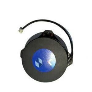
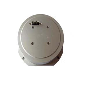
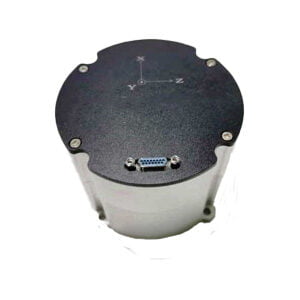
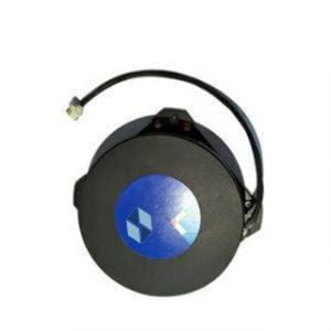
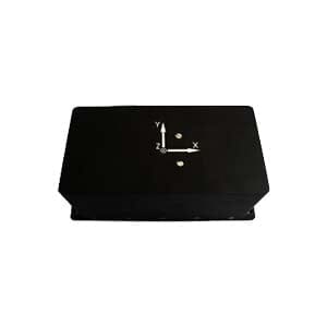
We use fiber optic gyroscope to measure the Angle, and change the transfer equation between the track direction by the Angle of the track detector, so as to obtain the track direction irregularity data. Ericco has high performance, low cost fiber optic gyro, like ER-FOG-851, ER-FOG-910, pure solid state fiber optic gyro, long life, if you want to get more technical data, please feel free to contact us.
More Technical Questions
1.Interferometric Fiber Optic Gyro
2.Temperature Drift and Compensation Method of FOG Gyro
3.Analysis of Fiber Optic Gyroscope Output Signal
4.Research on miniaturization technology of fiber optic gyroscope
5.Application of fiber optic gyroscope in aviation field
6.Analysis of Temperature Drift Compensation Method for Fiber Optic Gyroscope
Products in Article
