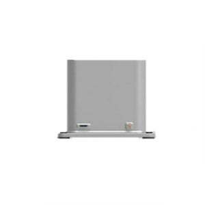
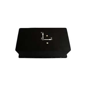
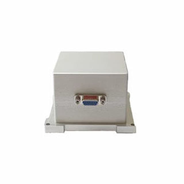
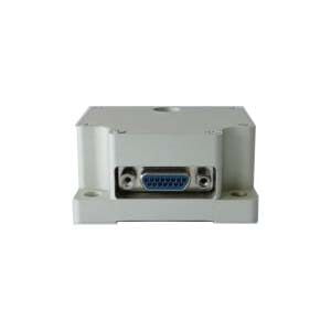
Inertial north-seeking technology is an important part of the field of inertial technology. The gyro north seeker measures the angular velocity component of the earth's rotation and calculates and analyzes the north direction information of the carrier.The north seeker can quickly and independently determine the orientation in all weather and all directions without any external information, and has the ability to quickly and accurately measure the true north of the local geography. The north finding device is composed of gyroscope, accelerometer, data acquisition and processing system and other components. Whether it is the device itself or the installation process, errors may occur, affecting the accuracy of north-seeking. Therefore, I will analyze the error sources and main error factors that affect the north-finding accuracy.
1.Main error sources
There are many errors that affect the accuracy of the north seeker, such as gyro platform leveling error, inertial device error, inertial device installation error, gyroscope indexing error, errors caused by base instability, scale factor errors, harmful acceleration and latitude errors. Quote, the multi-position north-seeking error, geophysical quantity error and transposition control error generated by the accelerometer, etc., among which the inertial device error includes fiber optic gyroscope error and accelerometer error. The main error terms include constant error, random drift and noise; inertial device The installation error includes the misalignment error between the fiber optic gyroscope and the north-seeking coordinate system; the following is a detailed analysis of the errors that affect the accuracy of the north-seeking instrument, and proposes corresponding compensation methods.
2.Error and compensation of inertial devices in north seeking system
2.1Error compensation of gyro sensor
(1)Establishment of gyro error model
The accuracy of the gyro determines the north-seeking accuracy of the north-seeking system and the tracking accuracy of strapdown inertial navigation. Therefore, the system must perform error compensation on the gyroscope.This article adopts the error model as shown in formula (1): 
In formula (1), ωvx, ωvy, and ωvz are the actual output values of the gyro angular velocity, and ωx, ωy, and ωz are the theoretical input values of the gyro angular velocity. bgx, bgy, bgz are the constant zero bias of the gyro angular velocity, Sgx, Sgy, Sgz are the scale factors of the gyro angular velocity, mg, xy, mg, xz, mg, yx, mg, yz, mg, zx, mg, zy are The gyro angular velocities of the two axes cross influence each other.
In the gyro error model, the constant bias error of the gyro is equivalent to adding a constant value to the error model. The linear error, installation error and non-orthogonal error of the gyroscope are equivalent to the error model left multiplied by a 3 × 3 matrix.
(2)Calibration of model parameters
The model parameters are first calibrated through rate experiments to calibrate the scale factor of the gyroscope. During the test, the IMU was fixed on the rate turntable, set within the gyroscope measurement range, and provided excitation for the gyroscope at different rotational speeds, and the least squares method was used to solve the scale factor. After the scale factor is determined, its constant zero bias and cross-coupling term error coefficients are calibrated through the six-position test shown in the acceleration in Figure 2.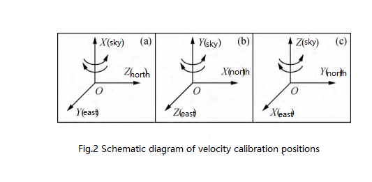
2.2Error compensation of acceleration sensor
(1) Establishment of acceleration error model
The inclination angle errors in the north-seeking system and the strapdown inertial navigation system, as well as the errors caused by the non-coincidence and non-orthogonality between the coordinate axes of the two systems and the installation axes, are all caused by the three-axis acceleration sensors in the respective systems. Therefore, if you want to obtain a high-precision tilt angle, you must compensate for the error of the three-axis acceleration sensor. Conventional acceleration sensor correction methods mostly use a linear error model and do not consider the mutual influence of each axis. Therefore, this article proposes a three-axis accelerometer error model as shown in Figure (3):
In the formula (3), fax, fby, and fcz are the actual output values of the three-axis acceleration, and f'ax, f'by, and f'cz are the theoretical output values of the three-axis acceleration. Sax, Sby, Scz are the scale factors of the three-axis acceleration sensor, ma, xy, ma, xz, mb, yx, mb, yz, mc, zx, mc, zy are the mutual cross-influence coefficients of the two axes. Pax, Pby, and Pcz are the constant zero deviations of acceleration, and Paxi, Pbyi, and Pczi (i = 1, 2, 3) are the nonlinear error coefficients of quadratic and cubic acceleration. In the acceleration error compensation model, the constant bias error of acceleration is equivalent to adding a constant value to the error model. The linear error, installation error and non-orthogonal error of acceleration are equivalent to the error model left multiplied by a 3 × 3 matrix.
The acceleration sensor maintains linear output within a small angle range; for large angles, the acceleration sensor maintains nonlinear characteristics, so a two- or three-cubic acceleration nonlinear error coefficient is added to the error compensation model to improve the accuracy of large angles. Inclination angle measurement accuracy.
(2)Calibration of model parameters
In order to determine the parameters of the error model in formula (3), a multi-position method can usually be used to solve it. For a single position, the actual values of the three-axis acceleration fax, fby, fcz and the theoretical values of f'ax, f'by, f'cz in formula (3) are known, and three equations can be obtained. To obtain the 18 error coefficients in the model, they can be obtained from six single positions and the least squares method parameter estimation is used, as shown in Figure 4.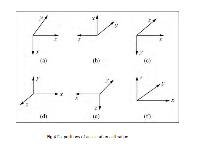
3.Conclusion
There are many errors that affect the accuracy of the north seeker. The article briefly analyzes the key errors and makes a corresponding compensation plan, which plays a great role in improving the accuracy of the north seeker. During the development and research process of the north finder, Ericco has been making continuous efforts to reduce the north finder error. It has two products in the fog north seeke: ER-FNS-02 and ER-FNS-03, which have high stability, the integration is reliable and worthy of your understanding and appreciation. Ericco welcomes your consultation!
More Technical Questions
1.Do You Know the FOG North Finder?
2.Application of MEMS Accelerometer in North Finder
3.Application of Fiber Optic Gyroscope North Finder
4.The Principle and Application of North Finder
5.The Structure of FOG North Finder
6.Application of North Finder in Mining Industry
Products in Article
