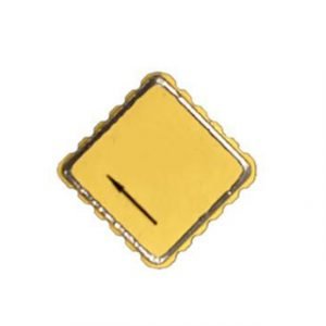
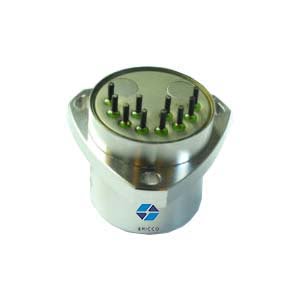
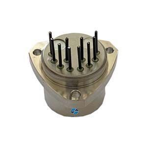
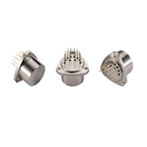
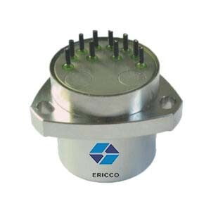
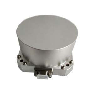
The accelerometer is a type of inertial sensor used to measure the specific force of the carrier along the input axis of the sensor. With the development of the inertia technology, accelerometers have been widely used in both commercial and military applications, for instance, aircraft, vehicle, missile, and aerospace applications. Compared with other types of accelerometers, the Q-Flex accelerometer shows superiorities in low cost, simple structure, high reliability, and relatively high accuracy. It has evolved into the most ideal type of accelerometers for INS
The Q-Flex accelerometer is a pendulous accelerometer designed base on Newton's second law. The core part of Q-Flex accelerometer is a pendulous disc structure made of pure quartz. Two flexible beams are used to connect the quartz pendulum plate and the outer frame. The deposited Au film on the surface of the pendulum and the fixed plates of yoke constitute a differential capacitance. The typical working principle of Q-Flex accelerometer is described in Figure 1. An inertial torque is generated at the end of the flexible beams, while the external acceleration is applied to the input axis (IA).
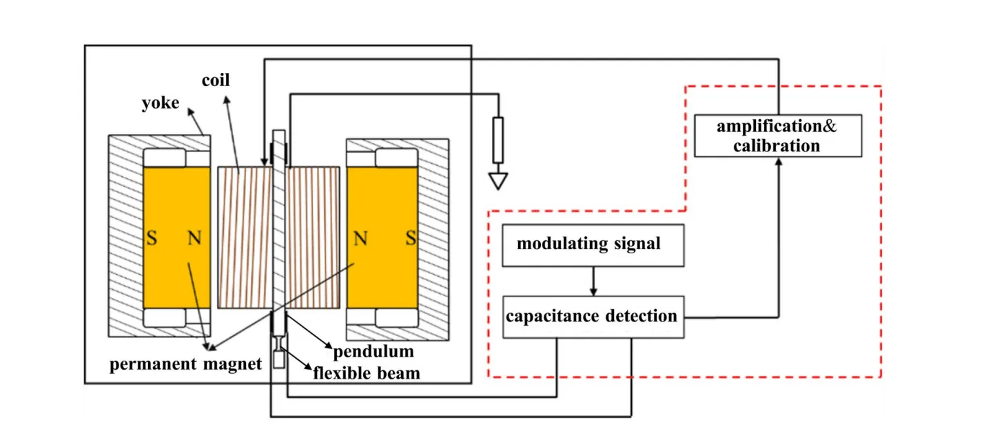
The angular displacement of the pendulum disk caused by an inertial torque is equivalent to the external acceleration under the micro-oscillation, and the capacitance differences caused by the angular displacement is proportional to the input acceleration. After the capacitance detection, the feedback current generated by the servo circuit is transferred to the torque coil. Then, the inertial torque is balanced with the electromagnetic torque generated by the Laplace force. If the capacitance differences go back to zero, the input acceleration could be obtained by measuring the feedback current.
The equation of motion for the pendulum disk is derived based on the Lagrange Equation (1).

where J is the moment of inertia for the pendulum disk about the output axis (OA), C is the damp in the working air gap, D is the bending stiffness of the flexible beams, P represents the pendulosity and is equal to m×L, where m is the mass of the pendulum disk and L is the arm of the inertial moment. θ is the deflection angle of the pendulum disk, α is the misalignment angle between IA and case reference IA about the pendulous axis (PA). ap, ai, and ao are the acceleration components along PA, IA, and OA, respectively. kT is the scale factor of the torquer, i is the feedback current. Md is the disturbing torque which cannot be measured accurately.
Considering that the quartz flexible accelerometers is working under the close‐loop condition, all the angles are small enough. Then, the block diagram of the digital close‐loop quartz flexible accelerometers system is displayed in Figure 2 based on Equation (1).

Fig.2 Loop model of digital close‐loop Quartz Flexible Accelerometer system.
Figure 2 shows that quartz flexible accelerometers is a second‐order linear system. The parameters k1, kCV, kAD, kDA, and kVI are the transfer factors of the modules in the Forward and Feedback Channels, respectively. D(s) is the controller to be designed. The relation between Dout(s) and ai is derived by ignoring the cross‐ coupling terms, given by Equation (2).

If the input acceleration and disturbing torque in Equation (2) are constant values, the output feedback current in a steady state is

where the coefficient of the first term on the right side in Equation (3) is defined as the scale factor of quartz flexible accelerometers. According to the common specification and dimension of a quartz flexible accelerometers, the bending stiffness D is far less than the product of all transfer factors in forward and feedback channels. As a result, the scale factor can be expressed approximately by Equation (4).

where KT is equal to the product of kT, kDA, and kVI, representing the transfer coefficient of the whole feedback channel. Without applying the controller and considering the disturbing torque, the damping ratio ζ of the pendulum itself is always greater than 1 based on the common structure parameters of the pendulum disk. In consequence, the designed controller D(s) is not complicated in form because of the overdamped property
Summary
Ericco provides high-precision quartz accelerometers, such as the ER-QA-01A3, with a bias stability of 10μg, scale factor repeatability of 10ppm, and a weight of 80g, which can be widely used in aircraft carrier microgravity measurement systems, inertial navigation systems, and static angle measurement systems.
More Technical Questions
1.Quartz Flexure Accelerometer Pendulum Processing Technology
2. Choosing an Accelerometer - MEMS or Quartz Accelerometer
3. Driving Automotive Evolution: MEMS Accelerometers
4. Factors Affecting the Stability of Q-Flex Accelerometers
5. Structure Design of High Precision Quartz Flexible Accelerometer
6. Methods to Maintain the Long-Term Performance of Quartz Flexure Accelerometers


