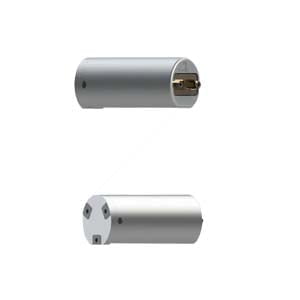
The fluxgate directional assembly is composed of an accelerometer sensor and a fluxgate sensor. In recent years, the drilling industry, as a technology-oriented industry, has undergone great changes. From the original mechanical driller to now a comprehensive multi-sensor multi-parameter drilling tool with electromechanical system control as the core. With the development of accelerometer sensor technology and fluxgate sensor technology, the measurement accuracy of fluxgate orientation assembly has been greatly improved. High-precision fluxgate directional assembly play a great role in special well operations such as horizontal well drilling and rotary steerable drilling.
In this paper, the design of fluxgate directional components is introduced from the overall architecture design, sensor calculation basis and the overall circuit module and signal processing module design.
Overall architecture design
The core of fluxgate directional assembly is fluxgate and accelerometer. With the development of technology and the improvement of accuracy, accelerometer sensors are widely used in navigation system and positioning system. Using single-chip technology, the accelerometer can be greatly reduced in size and power consumption. Therefore, this paper designs the fluxgate directional assembly system, and calculates the space attitude and orientation of the probe by using the accelerometer and fluxgate controlled by single chip microcomputer, combined with the earth's magnetic field and gravity field. FIG. 1 shows the overall operation flow chart of the fluxgate directional assembly system.
The accelerometer, fluxgate sensor and temperature sensor in the mine convert the analog signal to digital signal through data acquisition to the CPU in the mine. The downhole CPU uses the mud pulse to encode the data to the surface pressure sensor through the pulser. A computer on the surface takes measurements from pressure sensors and decodes them to retrieve the downhole data.
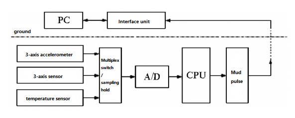
Figure 1 Operation flow chart of fluxgate directional components
Calculation basis of accelerometer and fluxgate
The accelerometer and fluxgate are mounted as a unit at the top of the fluxgate directional assembly, as shown in Figure 2. Three-axis accelerometer and three-axis fluxgate orthogonal in pairs. The three-axis accelerometer can measure the gravity component of the gravity field on each axis, and the inclination degree of the directional probe can be obtained through calculation. The triaxial fluxgate can measure the components of the geomagnetic field on the three orthogonal axes, and the inclination attitude of the directional probe in space can be obtained by calculation.
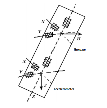
Figure 2 Schematic diagram of the installation of the accelerometer and fluxgate in the fluxgate directional components
Overall circuit module and signal processing module design
1. Overview of the power module
The power module provides a stable DC voltage to the sensors and control circuits. After being rectified by the pulser and pulse voltage rectifier module, the voltage is 30V, and the power module continues to convert the 30V voltage into ±13V and 7V direct current. Its working flow chart is shown in Figure 3. SNT input 30V DC through the field effect tube and voltage regulator diode voltage regulation, output stable 5V voltage to the main control, the main control operation amplifier is turned on, the power transformer starts to work, through the transformer coupling and rectification, the generation of stable ±13V voltage.
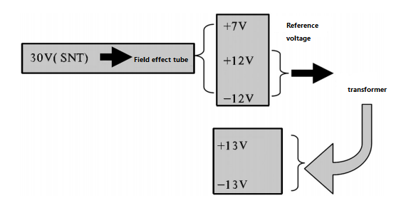
Figure 3 Working flowchart of the power module
2. Signal processing module details
The function of the signal processing module is to filter, shape and A/D conversion the signal transmitted by the sensor. Its working flow chart is shown in Figure 4.
The channel accelerometer signal and the 3-channel fluxgate signal are collected by the sensor and transmitted to the signal processing circuit board. After the signal processing circuit board filters and shapes it, the analog switch is input. The main control switch is on or off, allowing only one signal to pass through at the same time. The analog switch also performs A/D conversion on the signal.
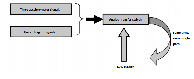
Figure 4 Working flow chart of signal processing board
Conclusion
This paper describes the design of fluxgate orientation assembly. It can be divided into normal temperature and high temperature according to the working temperature. For example, the ER-OS-07 is a wireless static measurement fluxgate directional assembly with an operating temperature of 150 ° C, while the ER-OS-07H increases the operating temperature on this basis, and can operate at a high temperature of 175 ° C. Because underground working environments are often harsh and high temperatures, directional components that can adapt to high temperatures and resist impact are needed to assist in the work.
If you are interested in other knowledge of fluxgate directional assembly, please contact us.
More Technical Questions
1.Fluxgate Directional Assembly: The Working Principle of Fluxgate
2.How Do Fluxgate Directional Assembly work in MWD
3.Application of Fluxgate In Fluxgate Directional Assembly
4.The Accelerometer And Fluxgate In The Fluxgate Directional Assembly
5.Sensor Calibration In Fluxgate Directional Assembly
6.What Is The Principle Of MWD?
Products in Article
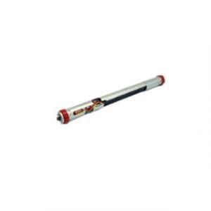
Dynamic Fluxgate Directional Assembly
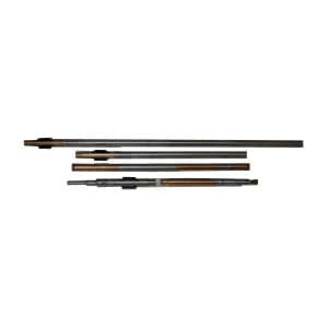
 High Precision Fluxgate Directional Assembly
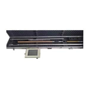
 High Temperature Fluxgate Directional Assembly