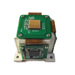
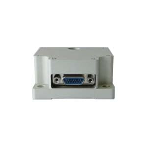
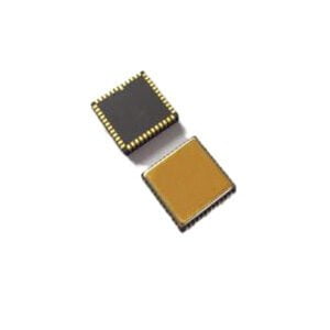
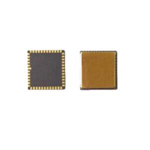
MEMS gyroscope is an important device for measuring carrier angular rate. It has the advantages of small size, low cost and low power consumption. However, single-axis MEMS gyros can only measure the angular speed of one axis, while three-axis MEMS gyroscopes can measure the angular speed of three axes, so three-axis MEMS gyroscopes have become the main development direction of the industry.
There are three integration methods of three-axis MEMS gyroscope: three-axis gyro orthogonal integration method, single-chip single-structure three-axis gyro method and single-chip multi-structure gyro array method. In the last article, we covered these three integration approaches in detail, and this article will explore how they compare.
Case study
1. University of California, Irvine (UCI) proposed two types of single-chip three-axis MEMS gyroscopes with angular vibration. The structure is shown in Figure 1. The driving mode and Z-axis rate detection modes are in-plane motion, and the X-axis and Y-axis angular rate detection modes are out-of-plane motion. Structure I (FIG.1 (a)) is 1.49mm × 0.8mm in size, and the scale factors of X, Y and Z axes are 0.12µV /°/s, 0.09µV /°/s and 0.3µV /°/s. The driving mode resonance frequency of the structure is 67410 Hz. The detection mode resonant frequencies of X, Y and Z axes are 63260 Hz, 63430 Hz and 65000 Hz respectively.
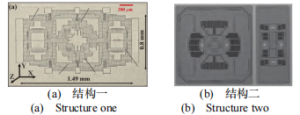
Figure 1 Two structures of monolithic three-axis gyroscope proposed by University of California, Irvine
2. University of California, Davis (UCD) proposed a single-chip three-axis MEMS gyroscopein the form of four-mass block line vibration. Its structure is shown in Figure 2, with a thickness of 22.2μm and an area of 3.2mm × 3.2mm. The scale factors of the X, Y and Z axes are 28.5µV /°/s, 57.8µV /°/s and 19.4µV /°/s. The structural drive mode resonant frequency is 27964 Hz, and the detection mode resonant frequency of the X, Y and Z axes is 25901 Hz, respectively. 27115 Hz and 30559 Hz. Zero-bias stability for the X, Y, and Z axes is 0.016 °/s, 0.004 °/s, and 0.043 °/s.
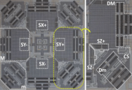
Figure 2 Structure of monolithic three-axis gyroscope proposed by University of California, Davis
3. Georgia Institute of Technology (GIT) of the United States proposed a four-mass monolithic three-axis MEMS gyroscope, as shown in Figure 3, with an area of 1.428 mm×1.428 mm and a scaling factor of 1.4 pA/°/s, 1.2 pA/°/s and 30.5 pA/°/s in the three axes of X, Y and Z. The resonant frequencies and quality factors of the structural drive modes, X-axis, Y-axis and Z-axis detection modes are 138058Hz, 139140Hz, 139048Hz and 138043Hz, 3910, 1181, 1360 and 505, respectively. The bias stability and angular random walk for the X, Y and Z axes were 0.226 °/s, 0.166 °/s and 0.041 °/s, 0.292 °/√s, 0.357 °/√s and 0.028 °/√s, respectively.
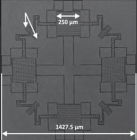
Figure 3 Structure of monolithic three-axis gyroscope proposed by Georgia Institute of Technology
4. Singapore Institute of Science and Technology (ASTR) proposed a combination sensor array of three-axis gyroscope and three-axis accelerometer, in which the X-axis and Y-axis gyroscope adopted the form of angular vibration, and the Z-axis gyroscope adopted the form of line vibration, and its structure was shown in Figure 4. The three axis ranges of the gyroscope are 1000 °/s, and the X-axis, Y-axis and Z-axis scale factors, nonlinearity, zero-bias stability and angular random walk are respectively: LSB / 5.01 ° s, 5.09 LSB / ° LSB / ° / s/s and 12.91, 0.2%, 0.8% and 0.6%, 0.07 ° s, 0.04 ° and 0.03 ° s/s, 0.17 ° s /), 0.14 ° s and s, 0.04 ° /) /) The structure size is 2.0mm × 2.0mm × 0.5mm.

Figure 4 Three-axis gyro array proposed by Agency for Science, Technology and Research, Singapore
5. University of California, Irvine (UCI) proposed a folding micromechanical array of three-axis gyroscope and three-axis accelerometer, which mainly adopts the way of micro-assembly, as shown in Figure 5. The gyro structure adopts a single axis mode, including ring and line vibration forms, and the overall folded shape is also proposed in hexahedron and pyramid shape. The integrated circuit can be configured in the center space of the folded shape without breaking the external shape and configuration. After testing, the scale factor, Angle random walk, bias stability and orthogonal error of ring gyroscope (structure diameter 2.8mm) and line vibration gyroscope (structure area 3.1mm × 3.1mm) used for assembly are respectively: 1.1 mV / ° / s and 1.94 mV / ° / s, 0.78 ° /) h/h and 0.11 °), 17 ° and 1.3 ° / h/h, 237 ° / s and the 404 ° / s.
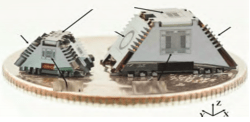
Figure 5 Folding structure of three-axis gyroscope array proposed by University of California, Irvine
Summary of parameters of three-axis MEMS gyroscope
| UCI | UCD | GIT | ASTR | UCI | ||
| Structural form | Single structure | Single structure | Single structure | Two-structure array | Three-structure
folded array |
|
| Mode of vibration | Linear vibration | Linear vibration | Linear vibration | Angular vibration+Linear vibration | Ring or line vibration | |
| Size (mm) | 1.2mm2 | 3.2×3.2 | 1.4×1.4 | 2×2 | diameter 2.8
or 3.1×3.1 |
|
| Resonant frequency
(Hz) |
drive | 67410 | 27964 | 138058 | - | - |
| X axis | 63260 | 25901 | 139140 | - | - | |
| Y axis | 63430 | 27115 | 139048 | - | - | |
| Z axis | 65000 | 30559 | 138043 | - | - | |
| Scale factor | X axis | 0.12µV/°/s | 28.5µV/°/s | 1.40pA/°/s | 5.01LSB/°/s | 1.1(1.94)mV/°/s |
| Y axis | 0.09µV/°/s | 57.8µV/°/s | 1.2pA/°/s | 5.09LSB/°/s | ||
| Z axis | 0.3µV/°/s | 19.4µV/°/s | 30.5pA/°/s | 12.9LSB/°/s | ||
| Measuring range (°/s) | ±50 | 300 | 130 | 1000 | - | |
| Quality factor | drive | 34000 | 9840 | 3910 | - | - |
| X axis | 53000 | 927 | 1181 | - | - | |
| Y axis | 45000 | 989 | 1360 | - | - | |
| Z axis | 36000 | 6744 | 505 | - | - | |
| Angular random walk (°/s/√Hz ) | X axis | 0.06 | 0.023°/s | 0.292°/√s | 0.17°/√s | 0.78(0.11)°/√h |
| Y axis | 0.12 | 0.01°/s | 0.357°/√s | 0.14°/√s | ||
| Z axis | 0.048 | 0.036°/s | 0.028°/√s | 0.04°/√s | ||
| Bias stability | X axis | 0.033°/s | 0.043°/s | 0.226°/s | 0.07°/s | 17(1.3)°/h |
| Y axis | 0.039°/s | 0.016°/s | 0.166°/s | 0.04°/s | ||
| Z axis | 0.013°/s | 0.004°/s | 0.041°/s | 0.03°/s | ||
Table 1 Summary of representative parameters of triaxial MEMS gyro research
It can be seen from Table 1 that the single structure has obvious advantages in terms of plane size, and the gyro resonance frequency ranges from 6 kHz to 140 kHz. In terms of accuracy, the Angle random walk index of the array triaxis gyro can achieve higher precision than that of the single triaxis gyro, and the zero bias stability index of the array triaxis gyro is obviously better than that of the single triaxis gyro structure. At the same time, although there is no cross-comparison data for the aspects of inter-axis coupling and orthogonal error, the array structure should be superior to the single three-axis structure from the aspects of structural complexity and processing difficulty.
In addition, in terms of gyro reliability, since the single-structure three-axis gyro structure is an integral design, if a certain structure (such as the support beam) breaks, all three axial gyros will fail; while in the array structure, if a beam breaks, one axis or two axes will fail, and the rest of the structure can work normally. This makes the reliability of the array type better than that of the single structure of the three-axis gyro.
Comparison of three axis MEMS gyroscope integration methods
Through the analysis and summary of the above three-axis MEMS gyroscope, it can be seen that although the three methods can realize the function of three-axis gyroscope, each of the three methods has advantages and disadvantages, and the relevant comparison is summarized in Table 2 in this paper: The advantages and disadvantages of the two schemes of "three single-axis gyro orthogonal integration method" and "single-chip single-structure three-axis gyro method" are basically complementary, while the "single-chip multi-structure gyro array method" adopts the way of simple gyro structure plane overall arrangement and simultaneous processing, and uses mature structure and mature technology to solve the problem. It takes into account the advantages of simple structure, easy processing, high reliability, simple decoupling and high precision, and also meets the advantages of small volume, low cost and easy protection of the "single piece single structure three-axis gyro method".
| Mode | volume | structure | cost | precision | process | defense | reliable | error | decoupling |
| Orthogonal integration of three single axis gyro | max | easy | max | The highest | easy | difficult | high | big | easy |
| Single-chip single-structure three-axis gyro method | small | complexity | low | low | hardest | easy | worst | big | hard |
| Monolithic multi-structure gyro array method | small | easy | low | high | easy | easy | high | small | easy |
Table 2 Comparison of integration methods for three-axis MEMS gyroscopes
Conclusion
"Three single-axis gyroscope orthogonal integration method" is a method widely used at present, and the study of this scheme has become an engineering problem. This method mainly relies on the orthogonal placement of three single-axis gyroscopes, and its performance is determined by a single gyroscope, which can achieve relatively high precision. However, in terms of volume, assembly error, packaging and processing cost, this method has obvious disadvantages. This is the case with the ER-3MG-03, a three-axis MEMS gyroscope for navigation and stability control. The main function of the ER-3MG-07 is also stability control, but their platform body is different.
"Single-chip single-structure three-axis gyro method" is the research hotspot of various units at present, which mainly covers the research of new structure forms, new technology methods, new integrated circuits and so on. The method has the smallest volume, the highest integration, and the lowest packaging and processing costs. However, in view of the current processing technology level, the structure of this method is relatively complex, resulting in greater processing difficulty, low yield and poor consistency. Moreover, due to the complexity of vibration forms, there are more difficulties in signal decoupling and multi-structure control in the later stage, and it is difficult to move to the application field of mass production in a short period of time.
"Single-chip multi-structure gyro array method" is a practical compromise on the basis of the current processing technology. Its structure complexity is low, making the processing simpler and ensuring the yield. The planar integration scheme can greatly reduce the volume and improve the integration degree. Due to its small structure and high integration, its packaging cost is also low.
If you want to know more about three-axis MEMS gyro, please contact us.
More Technical Questions
1.Integrated method of three-axis MEMS gyroscope
2.Main features of MEMS gyroscope
3.Bandwidth test method of MEMS gyroscope
4.Impact resistance technology of MEMS gyroscope
5.Research on driving mode of MEMS gyroscope
6.Research on scale factor nonlinearity of MEMS gyroscope
Products in Article
