In a GNSS/INS integrated navigation system, GNSS measurements play a critical role in correcting the INS. Therefore, the proper functioning of the integrated system depends on the continuity and stability of the satellite signals. However, when the system operates under overpasses, tree canopies, or within urban buildings, the satellite signals can easily be obstructed or interfered with, potentially leading to a loss of lock in the GNSS receiver.This article discusses solutions for maintaining the accuracy and stability of GNSS/INS integrated navigation systems when satellite signals are lost.
When the satellite signal is unavailable for an extended period, the lack of GNSS corrections causes the INS errors to accumulate rapidly, especially in systems with lower-precision inertial measurement units. This issue leads to a decline in the accuracy, stability, and continuity of the integrated system's operation. Consequently, it is essential to address this problem to enhance the robustness of the integrated system in such complex environments.
1.Two Main Solutions to Address Signal Loss of GNSS/INS
Currently, there are two main solutions to address the scenario of satellite signal loss.
Solution 1: Integrate Additional Sensors
On one hand, additional sensors can be integrated into the existing GNSS/INS system, such as odometers, LiDAR, astronomical sensors, and visual sensors. Thus, when satellite signal loss renders the GNSS unavailable, the newly added sensors can provide measurement information and form a new integrated system with the INS to suppress the accumulation of INS errors. The issues with this approach include increased system costs due to the additional sensors and potential design complexity if the new sensors require complex filtering models.
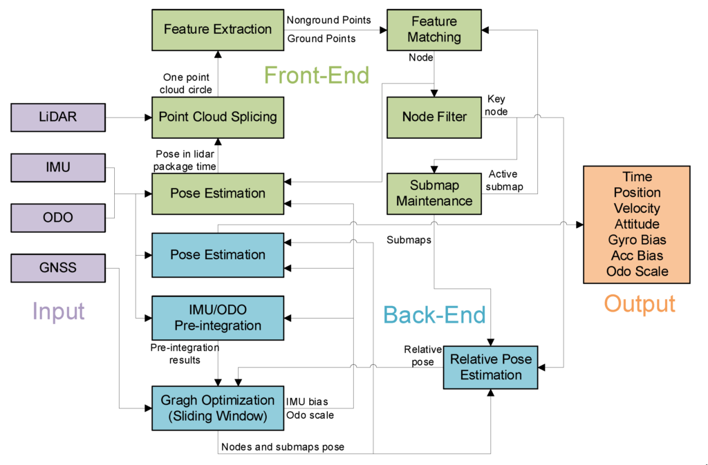
Fig.1 System overview of the GNSS IMU ODO LiDAR SLAM integrated navigation system.
Solution 2: ZUPT Technology
On the other hand, a positioning model with motion state constraints can be established based on the motion characteristics of the vehicle. This method does not require adding new sensors to the existing integrated system, thus avoiding extra costs. When GNSS is unavailable, the new measurement information is provided by the motion state constraints to suppress the INS divergence. For example, when the vehicle is stationary, zero-velocity update (ZUPT) technology can be applied to suppress the accumulation of INS errors.
ZUPT is a low-cost and commonly used method to mitigate INS divergence. When the vehicle is stationary, the vehicle's speed should theoretically be zero. However, due to the accumulation of INS errors over time, the output speed is not zero, so the INS output speed can be used as a measurement of the speed error. Thus, based on the constraint that the vehicle's speed is zero, a corresponding measurement equation can be established, providing measurement information for the integrated system and suppressing the accumulation of INS errors.
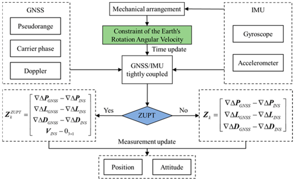
Fig.2 The flowchart of the ZUPT-based GNSSIMU tightly coupled algorithm with CERAV.
However, the application of ZUPT requires the vehicle to be stationary, making it a static zero-velocity update technology that cannot provide measurement information during normal vehicle maneuvers. In practical applications, this requires the vehicle to frequently stop from a moving state, reducing its maneuverability. Additionally, ZUPT requires accurate detection of the vehicle's stationary moments. If detection fails, incorrect measurement information may be provided, potentially leading to the failure of this method and even causing the integrated system's accuracy to decline or diverge.
Conclusion
The loss of satellite signals can cause rapid error accumulation in the INS, particularly in complex environments like urban areas. Two main solutions are presented: adding additional sensors, such as LiDAR or visual sensors, to provide alternative measurements, or using motion state constraints like Zero-Velocity Update (ZUPT) technology to correct INS errors. Each approach has its own advantages and challenges, with sensor integration increasing costs and complexity, while ZUPT requires the vehicle to be stationary and accurately detected to be effective.
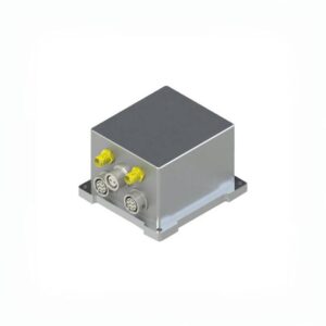
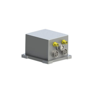
Ericco is at the forefront of inertial navigation technology and has recently introduced three GNSS-aided MEMS INS products with varying levels of accuracy (mapping level, tactical level, and industrial level). Notably, the mapping level MEMS GNSS/INS ER-GNSS/MINS-01 features a 0.02°/hr bias instability and a 0.005°/√hr angular random walk, along with a high-precision MEMS accelerometer with a large range (±60g, zero bias instability <2μg).
More Technical Questions
1. What Is GNSS-aided MEMS INS and How Does It Work?
2. How to Improve the Performance of MEMS Inertial Navigation Systems?
3. Why Should We Use MEMS GNSS/INS?
4. Classification And Performance Improvement Of MEMS Gyroscope
5. MEMS Accelerometer Packaging Technology
6. Performance Analysis of GNSS RTK Timing


