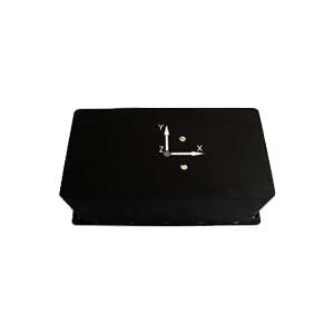
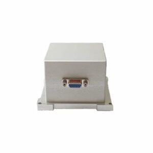
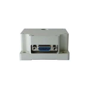
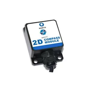
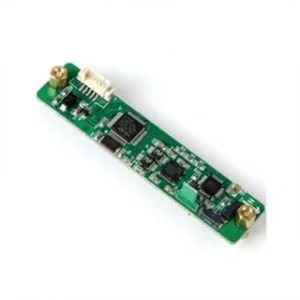
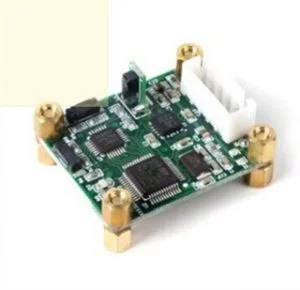
As an ideal inertial device for north finder, fiber optic gyroscope has many advantages such as light weight, small size, solid state and easy integration. With the continuous improvement of the performance level of fiber optic gyroscope in China, the fiber optic gyroscope north finder has broad development prospects and high research value, especially in the field of middle and low precision, the fiber optic gyroscope north finder has been popularized and applied.
High precision orientation is a prerequisite for the strike accuracy of modern land weapons, especially land-based long-range weapons. Orientation accuracy is an important factor to ensure the lethality of weapons within the range. As one of the important achievements in the application of inertial technology, Gyro north seeker has high orientation accuracy, short measurement time, is not restricted by climatic conditions, and can measure the orientation independently in all weather without relying on any external information. It is the preferred equipment for high-precision orientation reference system. High precision and fast north finding technology is not only an important guarantee technology to ensure rapid maneuvering and precise strike of weapon systems in modern war, but also a necessary technical means in civilian fields such as geophysical exploration, coal mining, geodesy, tunnel construction and oil mines.
1.The error mechanism of north finder
The error mechanism of the north seeker is analyzed from two aspects: the error of the inertia device includes the measurement error of the fiber optic gyro and the measurement error of the accelerometer, and the system error of north seeker includes the installation error, the Angle measurement error and the latitude error. This paper mainly analyzes the errors caused by inertial devices.
2.Inertial device error
(1) Fiber optic gyroscope measurement error
The measurement error of the fiber optic gyroscope includes the scale factor error of the gyroscope and the zero deviation drift error. It can be seen from equation (15) that the calculation formula of azimuth A does not contain the scale factor K. Therefore, when the scale factor error of the fiber optic gyroscope is constant, the north seeking accuracy of the north seeker is not affected by the scale factor error of the gyroscope, so the measurement error of the fiber optic gyroscope mainly refers to the zero deviation drift error of the gyroscope.
The influence of zero deviation drift of fiber optic gyroscope on the north seeking accuracy is related to the tilt Angle of the platform, the local geographical latitude and the north seeking azimuth. Assuming that the pitch Angle β and roll Angle α of north seeker are both 0° and latitude = 45°, the maximum north finding error caused by the zero deviation change rate of the fiber gyroscope ε= 0.01°/h is about 0.027°. The zero bias drift of fiber optic gyroscope is greatly affected by the starting performance, temperature performance, electricity and magnetic field of fiber optic gyroscope. In the case of fast north finding, the gyro drift is the main factor affecting the north finding accuracy.
(2) Accelerometer measurement error
It can be seen from equation (1) that the zero bias drift of the accelerometer mainly affects the calculation of pitch Angle β and roll Angle α of north seeker. By derivation of α and β respectively, equation (1) can obtain:

The calculation error of the tilt of north finder is related to the size of the tilt angle of north seeker, the local geographical latitude and the azimuth of north finder. The calculation error of tilt angle caused by the zero deviation of the accelerometer =100μg can be calculated from the above column. It is assumed that the true pitch Angle β and roll Angle α of the north finder are 0° and the latitude =45°. Then the maximum north finding error caused by zero bias of the accelerometer is about 0.0057°, that is, in this case, the maximum north finding error is equal to the inclination angle measurement error. The zero bias drift of accelerometer is mainly affected by temperature. When north seeking time is short, the temperature change is small, and the zero bias drift of accelerometer is generally less than 100μg during the north seeking process. After temperature compensation, the accelerometer will further improve the measurement accuracy.
Summary
Taking the land fiber optic gyro north finder as the research object and the four-position north finder method as an example, the error mechanism of the fiber optic north finder is analyzed in detail. The analysis conclusion shows that the zero deviation error of the gyro and the error of the internal component are the error sources of the fiber optic north finder. The analysis results in this paper provide a theoretical basis for the design of the optical fiber north finder. In the medium and high precision applications, the precision of the north finder can be effectively improved by selecting the fiber optic gyro with good performance, calibrating the installation error and improving the Angle measurement accuracy. At present, Ericco's optical fiber north finder is the advantage of low-cost three-axis FOG north finder ER-FNS-03, if you are interested, you can discuss with us.
More Technical Questions
1.Effective combination of north finder and spacecraft based on autonomous orientation
2.Research on downhole north seeker
3.Research on orthogonal monitoring technology of north finder
4.Modeling and filtering in signals collected by FOG north seekers
5.Error Modeling and Compensation Analysis of North Finder Based on FFT
6.Research and use of north finder for mining drilling rigs
Products in Article
