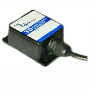
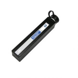
Electronic compasses, also called digital compasses, are a method of using the Earth's magnetic field to determine the North Pole, and have been widely used as navigation instruments or attitude sensors. In ancient times, it was called compass, and the magneto-resistance sensor produced by modern advanced processing technology provides a powerful help for the digitalization of compass. Nowadays, electronic compasses are generally machined from chips such as magneto-resistive sensors or fluxgates. It can be used in horizontal and vertical hole measurement, underwater exploration, aircraft navigation, scientific research, education and training, building positioning, equipment maintenance, navigation system and other fields.
Compared with the traditional pointer type and balance frame structure compass, the digital compass has low energy consumption, small size, light weight, high precision and miniaturization. Its output signal can be digitally displayed through processing. It can not only be used for pointing, but also the digital signal can be directly sent to the automatic rudder to control the ship's operation. At present, the three-axis strap-down magnetic resistance digital magnetic compass is widely used. This kind of compass has the advantages of anti-shaking and anti-vibration, high heading accuracy, electronic compensation for interference field, and can be integrated into the control loop for data link, so it is widely used in aviation, aerospace, robotics, navigation, vehicle autonomous navigation and other fields.
1.The constitution of an electronic compass
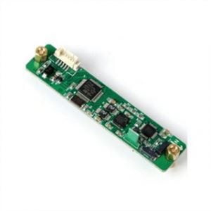
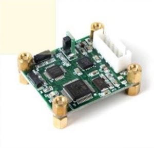
The three-dimensional electronic compass ER-EC-360A is composed of a three-dimensional reluctance sensor, an inclination sensor and an MCU. The 3D magneto-resistive sensor is used to measure the earth's magnetic field, and the inclination sensor is used to compensate the non-horizontal state of the magnetometer. The MCU processes signals from magnetometers and tilt sensors as well as data output and soft and hard iron compensation. The magnetometer is based on three vertical magneto-resistive sensors, each axial sensor detects the strength of the geomagnetic field in that direction.
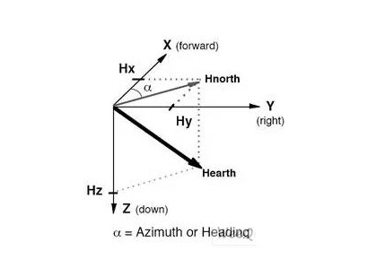
The sensor in the forward direction called the x direction detects the vector value of the geomagnetic field in the x direction, and the sensor in the right or Y direction detects the vector value of the geomagnetic field in the Y direction. Sensors in the down or Z direction detect the vector value of the Earth's magnetic field in the Z direction.
The sensitivity of the sensors in each direction has been adjusted to the optimum point based on the component vector of the geomagnetic field in that direction and has very low cross-axis sensitivity. The analog output signal generated by the sensor is amplified and sent to MCU for processing.
2.The following part of the hardware and principles are introduced
1)Magnetometer: Since the geomagnetic field is a vector, at a certain point, this vector can be broken down into two components parallel to the local level and one component perpendicular to the local level. So if you keep the compass module parallel to the local level the three axes of the magnetometer correspond to these three components. At present, the module is parallel to the horizontal plane by the Angle compensation, and then the heading Angle is calculated by the compensated data.
2) Accelerometer: The acceleration can be calculated from the three-axis data, which has advantages in static stability.
3)Kalman filtering is an algorithm that optimally estimates the state of a system by using linear system state equation and observing system input and output data. Since the observation data includes the effects of noise and interference in the system, the optimal estimation can also be regarded as a filtering process.
In radar, for example, one is interested in tracking a target, but measurements of the target's position, speed, and acceleration are often noisy at all times. Kalman filter uses the dynamic information of the target, tries to remove the influence of noise, and gets a good estimate of the target position. This estimate can be an estimate of the current target location (filtering), an estimate of the future location (prediction), or an estimate of the past location (interpolation or smoothing).
Summary
In addition to the three-axis electronic compass, Ericco company has a wealth of electronic compass types, such as low-cost two-axis electronic compass ER-EC-220, high-precision two-axis electronic compass ER-EC-225CAN, etc., they have been strictly tested, in extremely harsh environments can also provide accurate course data. If you have the need for digital compass, freely to contact us.
More Technical Questions
1.Electronic compass dynamic heading error correction
2.Soft Magnetic Error Compensation Method of Electronic Compass
3.Electronic Compass Hard Magnetic Error Compensation
4.Application of Gyroscope in Electronic Compass
5.Principle of digital compass
6.What Is The Difference Between Gyro Error and Compass Error in Navigation?
Products in Article
